
 1 year warranty


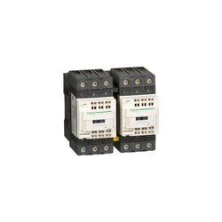
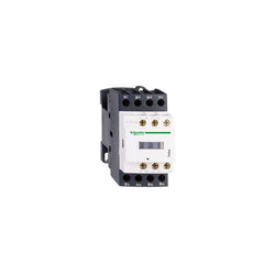
TeSys D reversing contactor - 3P(3 NO) - AC-3 - <= 440 V 40 A - 500 V AC coil
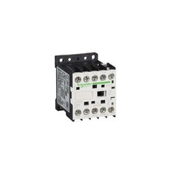
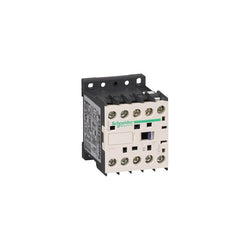
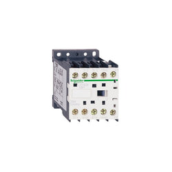
TeSys K contactor - 3P - AC-3 <= 440 V 12 A - 1 NO aux. - 110 V DC low
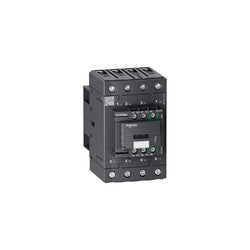
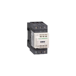
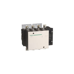
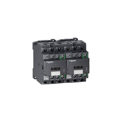
TeSys D contactor 4P 60A AC-1 up to 440V coil 100-250V AC/DC Everlink
Main
| Characteristic | Value(s) |
|---|---|
| Range | TeSys |
| Range of Product | TeSys Deca |
| Product or Component Type | Contactor |
| Device short name | LC1D |
| Contactor application | Motor control Resistive load |
| Utilisation category | AC-1 AC-4 AC-3 |
| Poles description | 3P |
| [Ue] rated operational voltage | Power circuit <= 690 V AC 25...400 Hz Power circuit <= 300 V DC |
| [Ie] rated operational current | 50 A (at <140 °F (60 °C)) at <= 440 V AC AC-3 for power circuit 80 A (at <140 °F (60 °C)) at <= 440 V AC AC-1 for power circuit |
| [Uc] control circuit voltage | 480 V AC 60 Hz |
Complementary
| Characteristic | Value(s) |
|---|---|
| Motor power kW | 15 kW at 220...230 V AC 50/60 Hz (AC-3) 22 kW at 380...400 V AC 50/60 Hz (AC-3) 30 kW at 500 V AC 50/60 Hz (AC-3) 33 kW at 660...690 V AC 50/60 Hz (AC-3) 25 kW at 415 V AC 50/60 Hz (AC-3) 30 kW at 440 V AC 50/60 Hz (AC-3) 11 kW at 400 V AC 50/60 Hz (AC-4) |
| Maximum Horse Power Rating | 3 hp at 115 V AC 50/60 Hz for 1 phase motors 7.5 hp at 230/240 V AC 50/60 Hz for 1 phase motors 15 hp at 200/208 V AC 50/60 Hz for 3 phase motors 15 hp at 230/240 V AC 50/60 Hz for 3 phase motors 40 hp at 460/480 V AC 50/60 Hz for 3 phase motors 40 hp at 575/600 V AC 50/60 Hz for 3 phase motors |
| Compatibility code | LC1D |
| Pole contact composition | 3 NO |
| Protective cover | With |
| [Ith] conventional free air thermal current | 10 A (at 140 °F (60 °C)) for signalling circuit 80 A (at 140 °F (60 °C)) for power circuit |
| Irms rated making capacity | 140 A AC for signalling circuit conforming to IEC 60947-5-1 250 A DC for signalling circuit conforming to IEC 60947-5-1 900 A at 440 V for power circuit conforming to IEC 60947 |
| Rated breaking capacity | 900 A at 440 V for power circuit conforming to IEC 60947 |
| [Icw] rated short-time withstand current | 400 A 104 °F (40 °C) - 10 s for power circuit 810 A 104 °F (40 °C) - 1 s for power circuit 84 A 104 °F (40 °C) - 10 min for power circuit 208 A 104 °F (40 °C) - 1 min for power circuit 100 A - 1 s for signalling circuit 120 A - 500 ms for signalling circuit 140 A - 100 ms for signalling circuit |
| Associated fuse rating | 10 A gG for signalling circuit conforming to IEC 60947-5-1 100 A gG at <= 690 V coordination type 1 for power circuit 100 A gG at <= 690 V coordination type 2 for power circuit |
| Average impedance | 1.5 mOhm - Ith 80 A 50 Hz for power circuit |
| Power dissipation per pole | 3.7 W AC-3 9.6 W AC-1 |
| [Ui] rated insulation voltage | Power circuit 600 V CSA Power circuit 600 V UL Signalling circuit 690 V IEC 60947-1 Signalling circuit 600 V CSA Signalling circuit 600 V UL Power circuit 690 V IEC 60947-4-1 |
| Overvoltage category | III |
| pollution degree | 3 |
| [Uimp] rated impulse withstand voltage | 6 kV IEC 60947 |
| Safety reliability level | B10d = 1369863 cycles contactor with nominal load EN/ISO 13849-1 B10d = 20000000 cycles contactor with mechanical load EN/ISO 13849-1 |
| Mechanical durability | 6 Mcycles |
| Electrical durability | 1.45 Mcycles 50 A AC-3 <= 440 V 1.1 Mcycles 80 A AC-1 <= 440 V |
| Control circuit type | AC 60 Hz |
| Coil technology | Without built-in suppressor module |
| Control circuit voltage limits | 0.3...0.6 Uc (-40â¦158 °F (-40â¦70 °C)):drop-out AC 60 Hz 0.85...1.1 Uc (-40â¦140 °F (-40â¦60 °C)):operational AC 60 Hz 1...1.1 Uc (140â¦158 °F (60â¦70 °C)):operational AC 60 Hz |
| Inrush power in VA | 140 VA 60 Hz cos phi 0.75 (at 68 °F (20 °C)) |
| Hold-in power consumption in VA | 13 VA 60 Hz cos phi 0.3 (at 68 °F (20 °C)) |
| Heat dissipation | 4â¦5 W at 60 Hz |
| Operating time | 4...19 ms opening 12...26 ms closing |
| Connections - terminals | Control circuit: spring terminals 1 0.004 in² (2.5 mm²) - cable stiffness: flexible without cable end Control circuit: spring terminals 2 0.004 in² (2.5 mm²) - cable stiffness: flexible without cable end Power circuit: EverLink BTR screw connectors 1 0.002â¦0.05 in² (1â¦35 mm²) - cable stiffness: flexible without cable end Power circuit: EverLink BTR screw connectors 2 0.002â¦0.04 in² (1â¦25 mm²) - cable stiffness: flexible without cable end Power circuit: EverLink BTR screw connectors 1 0.002â¦0.05 in² (1â¦35 mm²) - cable stiffness: flexible with cable end Power circuit: EverLink BTR screw connectors 2 0.002â¦0.04 in² (1â¦25 mm²) - cable stiffness: flexible with cable end Power circuit: EverLink BTR screw connectors 1 0.002â¦0.05 in² (1â¦35 mm²) - cable stiffness: solid without cable end Power circuit: EverLink BTR screw connectors 2 0.002â¦0.04 in² (1â¦25 mm²) - cable stiffness: solid without cable end |
| Tightening torque | Power circuit 70.8 lbf.in (8 N.m) EverLink BTR screw connectors 0.04â¦0.05 in² (25â¦35 mm²) hexagonal 0.2 in (4 mm) Power circuit 44.3 lbf.in (5 N.m) EverLink BTR screw connectors 0.004â¦0.04 in² (2.5â¦25 mm²) hexagonal 0.2 in (4 mm) |
| Auxiliary contact composition | 1 NO + 1 NC |
| Auxiliary contacts type | Mechanically linked 1 NO + 1 NC IEC 60947-5-1 Mirror contact 1 NC IEC 60947-4-1 |
| Signalling circuit frequency | 25...400 Hz |
| Minimum switching voltage | 17 V for signalling circuit |
| Minimum switching current | 5 mA for signalling circuit |
| Insulation resistance | > 10 MOhm for signalling circuit |
| Non-overlap time | 1.5 ms on de-energisation between NC and NO contact 1.5 ms on energisation between NC and NO contact |
| Mounting Support | Plate Rail |
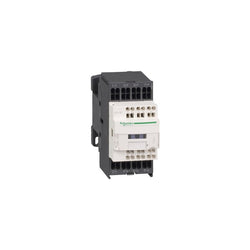
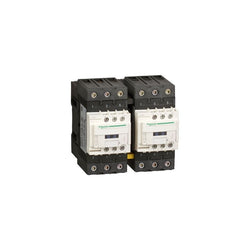
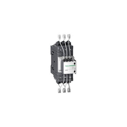
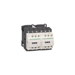
TeSys D contactor - 4P(4 NO) - AC-1 - <= 440 V 40 A - 24 V DC low cons coil
Main
| Characteristic | Value(s) |
|---|---|
| Range | TeSys |
| product name | TeSys Deca |
| Product or Component Type | Reversing contactor |
| Device short name | LC2D |
| Contactor application | Resistive load Motor control |
| Utilisation category | AC-1 AC-3 |
| Device presentation | Preassembled with reversing power busbar |
| Poles description | 3P |
| power pole contact composition | 3 NO |
| [Ue] rated operational voltage | Power circuit <= 690 V AC 25...400 Hz Power circuit <= 300 V DC |
| [Ie] rated operational current | 50 A (at <140 °F (60 °C)) at <= 440 V AC AC-3 for power circuit 80 A (at <140 °F (60 °C)) at <= 440 V AC AC-1 for power circuit |
| Motor power kW | 15 kW at 220...230 V AC 50 Hz 22 kW at 380...400 V AC 50 Hz 30 kW at 500 V AC 50 Hz 33 kW at 660...690 V AC 50 Hz 25 kW at 415 V AC 50 Hz 30 kW at 440 V AC 50 Hz |
| motor power HP (UL / CSA) | 3 hp at 115 V AC 60 Hz for 1 phase motors 7.5 hp at 230/240 V AC 60 Hz for 1 phase motors 15 hp at 200/208 V AC 60 Hz for 3 phase motors 15 hp at 230/240 V AC 60 Hz for 3 phase motors 40 hp at 460/480 V AC 60 Hz for 3 phase motors 40 hp at 575/600 V AC 60 Hz for 3 phase motors |
| Control circuit type | AC 50/60 Hz |
| [Uc] control circuit voltage | 115 V AC 50/60 Hz |
| Auxiliary contact composition | 1 NO + 1 NC |
| [Uimp] rated impulse withstand voltage | 6 kV IEC 60947 |
| Overvoltage category | III |
| [Ith] conventional free air thermal current | 10 A (at 140 °F (60 °C)) for signalling circuit 80 A (at 140 °F (60 °C)) for power circuit |
| Irms rated making capacity | 140 A AC for signalling circuit conforming to IEC 60947-5-1 250 A DC for signalling circuit conforming to IEC 60947-5-1 900 A at 440 V for power circuit conforming to IEC 60947 |
| Rated breaking capacity | 900 A at 440 V for power circuit conforming to IEC 60947 |
| [Icw] rated short-time withstand current | 400 A 104 °F (40 °C) - 10 s for power circuit 810 A 104 °F (40 °C) - 1 s for power circuit 84 A 104 °F (40 °C) - 10 min for power circuit 208 A 104 °F (40 °C) - 1 min for power circuit 100 A - 1 s for signalling circuit 120 A - 500 ms for signalling circuit 140 A - 100 ms for signalling circuit |
| Associated fuse rating | 10 A gG for signalling circuit conforming to IEC 60947-5-1 100 A gG at <= 690 V coordination type 1 for power circuit 100 A gG at <= 690 V coordination type 2 for power circuit |
| Average impedance | 1.5 mOhm - Ith 80 A 50 Hz for power circuit |
| [Ui] rated insulation voltage | Power circuit 690 V IEC 60947-4-1 Power circuit 600 V CSA Power circuit 600 V UL Signalling circuit 690 V IEC 60947-1 Signalling circuit 600 V CSA Signalling circuit 600 V UL |
| Electrical durability | 1.45 Mcycles 50 A AC-3 <= 440 V 1.1 Mcycles 80 A AC-1 <= 440 V |
| Power dissipation per pole | 3.7 W AC-3 9.6 W AC-1 |
| Front cover | With |
| Interlocking type | Mechanical |
| Mounting Support | Plate Rail |
| Standards | CSA C22.2 No 14 EN 60947-4-1 EN 60947-5-1 IEC 60947-4-1 IEC 60947-5-1 UL 508 |
| Product Certifications | GOST UL CCC CSA |
| Connections - terminals | Control circuit spring terminals 1 0.004 in² (2.5 mm²)flexible without cable end Control circuit spring terminals 2 0.004 in² (2.5 mm²)flexible without cable end Power circuit EverLink BTR screw connectors 1 0.002â¦0.05 in² (1â¦35 mm²)flexible without cable end Power circuit EverLink BTR screw connectors 2 0.002â¦0.04 in² (1â¦25 mm²)flexible without cable end Power circuit EverLink BTR screw connectors 1 0.002â¦0.05 in² (1â¦35 mm²)flexible with cable end Power circuit EverLink BTR screw connectors 2 0.002â¦0.04 in² (1â¦25 mm²)flexible with cable end Power circuit EverLink BTR screw connectors 1 0.002â¦0.05 in² (1â¦35 mm²)solid Power circuit EverLink BTR screw connectors 2 0.002â¦0.04 in² (1â¦25 mm²)solid |
| Tightening torque | Power circuit 70.8 lbf.in (8 N.m) EverLink BTR screw connectors 0.04â¦0.05 in² (25â¦35 mm²) hexagonal 0.2 in (4 mm) Power circuit 44.3 lbf.in (5 N.m) EverLink BTR screw connectors 0.004â¦0.04 in² (2.5â¦25 mm²) hexagonal 0.2 in (4 mm) |
| Operating time | 4...19 ms opening 12...26 ms closing |
| Safety reliability level | B10d = 1369863 cycles contactor with nominal load EN/ISO 13849-1 B10d = 20000000 cycles contactor with mechanical load EN/ISO 13849-1 |
| Mechanical durability | 6 Mcycles |
| Maximum operating rate | 3600 cyc/h 140 °F (60 °C) |
Complementary
| Characteristic | Value(s) |
|---|---|
| Coil technology | Without built-in suppressor module |
| Control circuit voltage limits | 0.3...0.6 Uc (-40â¦158 °F (-40â¦70 °C)):drop-out AC 50/60 Hz 0.8...1.1 Uc (-40â¦140 °F (-40â¦60 °C)):operational AC 50 Hz 0.85...1.1 Uc (-40â¦140 °F (-40â¦60 °C)):operational AC 60 Hz 1...1.1 Uc (140â¦158 °F (60â¦70 °C)):operational AC 50/60 Hz |
| Inrush power in VA | 140 VA 60 Hz cos phi 0.75 (at 68 °F (20 °C)) 160 VA 50 Hz cos phi 0.75 (at 68 °F (20 °C)) |
| Hold-in power consumption in VA | 13 VA 60 Hz cos phi 0.3 (at 68 °F (20 °C)) 15 VA 50 Hz cos phi 0.3 (at 68 °F (20 °C)) |
| Heat dissipation | 4â¦5 W 50/60 Hz |
| Auxiliary contacts type | Mechanically linked 1 NO + 1 NC IEC 60947-5-1 Mirror contact 1 NC IEC 60947-4-1 |
| Signalling circuit frequency | 25...400 Hz |
| Minimum switching current | 5 mA for signalling circuit |
| Minimum switching voltage | 17 V for signalling circuit |
| Non-overlap time | 1.5 ms on de-energisation between NC and NO contact 1.5 ms on energisation between NC and NO contact |
| Insulation resistance | > 10 MOhm for signalling circuit |

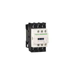
TeSys D contactor - 3P(3 NO) - AC-3 - <= 440 V 50 A - 380 V AC 50/60 Hz coil
TeSys Deca contactor, 3 poles (3NO), for switching 3-phase capacitor banks up to 30kVAR@400V 50Hz (50kVAR@690V). It provides a 380V 50/60 Hz AC coil, 1NO+2NC instantaneous auxiliary contacts, with front mounted early make poles and pre-wired damping resistors for current limitation. For operating rates until 240 cycles/hour and environments until 60°C, it procures high reliability and durability. Compact (55mm width), DIN-rail mounting or screw fixing. Multi standards certified (IEC, UL, CSA) and compliant with shunt capacitors standard IEC 60831, Green Premium product (RoHS/REACh).
Main
| Characteristic | Value(s) |
|---|---|
| Range | TeSys |
| product name | TeSys LC1D.K TeSys Deca |
| Product or Component Type | Capacitor duty contactor |
| Device short name | LC1DPK |
| Device Application | Control |
| Contactor application | Power factor correction |
| Utilisation category | AC-6b |
| Poles description | 3P |
| power pole contact composition | 3 NO |
| Device location in system | Line interruption Inside delta interruption |
| [Ue] rated operational voltage | Power circuit 690 V AC 50/60 Hz |
| Reactive power rating | 17 kvar 230 V AC 50 Hz 140 °F (60 °C) 30 kvar 400 V AC 50 Hz 140 °F (60 °C) 32 kvar 440 V AC 50 Hz 140 °F (60 °C) 50 kvar 690 V AC 50 Hz 140 °F (60 °C) 16.5 kvar 230 V AC 60 Hz 140 °F (60 °C) 33.3 kvar 460 V AC 60 Hz 140 °F (60 °C) 40 kvar 575 V AC 60 Hz 140 °F (60 °C) |
| Control circuit type | AC 50/60 Hz |
| [Uc] control circuit voltage | 380 V AC 50/60 Hz |
| Auxiliary contact composition | 1 NO + 2 NC instantaneous |
| Electrical durability | 300000 cycles 400 V 200000 cycles 690 V |
| Mounting Support | DIN rail Plate |
| Standards | EN/IEC 60947-1 EN/IEC 60947-4-1 UL 60947-4-1 CSA C22.2 No 60947-4-1 |
| Product Certifications | IECEE CB Scheme UL CSA |
| Connections - terminals | Control circuit: screw clamp terminals 1 0.002â¦0.006 in² (1â¦4 mm²) - cable stiffness: solid Control circuit: screw clamp terminals 2 0.002â¦0.006 in² (1â¦4 mm²) - cable stiffness: solid Control circuit: screw clamp terminals 1 0.002â¦0.006 in² (1â¦4 mm²) - cable stiffness: flexible without cable end Control circuit: screw clamp terminals 2 0.002â¦0.006 in² (1â¦4 mm²) - cable stiffness: flexible without cable end Control circuit: screw clamp terminals 1 0.002â¦0.006 in² (1â¦4 mm²) - cable stiffness: flexible with cable end Control circuit: screw clamp terminals 2 0.002â¦0.004 in² (1â¦2.5 mm²) - cable stiffness: flexible with cable end Power circuit: EverLink BTR screw connectors 1 0.002â¦0.05 in² (1â¦35 mm²) - cable stiffness: solid Power circuit: EverLink BTR screw connectors 2 0.002â¦0.04 in² (1â¦25 mm²) - cable stiffness: solid Power circuit: EverLink BTR screw connectors 1 0.002â¦0.05 in² (1â¦35 mm²) - cable stiffness: flexible with or without cable end Power circuit: EverLink BTR screw connectors 2 0.002â¦0.04 in² (1â¦25 mm²) - cable stiffness: flexible with or without cable end |
| Tightening torque | Control circuit 15.05 lbf.in (1.7 N.m) screw clamp terminals Power circuit 44.3 lbf.in (5 N.m) EverLink BTR screw connectors 0.002â¦0.04 in² (1â¦25 mm²) Power circuit 70.8 lbf.in (8 N.m) EverLink BTR screw connectors 0.05 in² (35 mm²) |
| Maximum operating rate | 100 cyc/h |
Complementary
| Characteristic | Value(s) |
|---|---|
| Auxiliary contacts type | Mechanically linked 1 NO + 2 NC IEC 60947-5-1 |
TeSys Deca contactor, 3 poles (3NO), for switching 3-phase capacitor banks up to 40kVAR@400V 50Hz (67kVAR@690V). It provides a 240V 50/60 Hz AC coil, 1NO+2NC instantaneous auxiliary contacts, with front mounted early make poles and pre-wired damping resistors for current limitation. For operating rates until 240 cycles/hour and environments until 60°C, it procures high reliability and durability. Compact (55mm width), DIN-rail mounting or screw fixing. Multi standards certified (IEC, UL, CSA) and compliant with shunt capacitors standard IEC 60831, Green Premium product (RoHS/REACh).
Main
| Characteristic | Value(s) |
|---|---|
| Range | TeSys |
| product name | TeSys LC1D.K TeSys Deca |
| Product or Component Type | Capacitor duty contactor |
| Device short name | LC1DTK |
| Device Application | Control |
| Contactor application | Power factor correction |
| Utilisation category | AC-6b |
| Poles description | 3P |
| power pole contact composition | 3 NO |
| Device location in system | Line interruption Inside delta interruption |
| [Ue] rated operational voltage | Power circuit 690 V AC 50/60 Hz |
| Reactive power rating | 22 kvar 230 V AC 50 Hz 140 °F (60 °C) 40 kvar 400 V AC 50 Hz 140 °F (60 °C) 43 kvar 440 V AC 50 Hz 140 °F (60 °C) 67 kvar 690 V AC 50 Hz 140 °F (60 °C) 20 kvar 230 V AC 60 Hz 140 °F (60 °C) 40 kvar 460 V AC 60 Hz 140 °F (60 °C) 50 kvar 575 V AC 60 Hz 140 °F (60 °C) |
| Control circuit type | AC 50/60 Hz |
| [Uc] control circuit voltage | 240 V AC 50/60 Hz |
| Auxiliary contact composition | 1 NO + 2 NC instantaneous |
| Electrical durability | 300000 cycles 400 V 200000 cycles 690 V |
| Mounting Support | DIN rail Plate |
| Standards | EN/IEC 60947-1 EN/IEC 60947-4-1 UL 60947-4-1 CSA C22.2 No 60947-4-1 |
| Product Certifications | IECEE CB Scheme UL CSA |
| Connections - terminals | Control circuit: screw clamp terminals 1 0.002â¦0.006 in² (1â¦4 mm²) - cable stiffness: solid Control circuit: screw clamp terminals 2 0.002â¦0.006 in² (1â¦4 mm²) - cable stiffness: solid Control circuit: screw clamp terminals 1 0.002â¦0.006 in² (1â¦4 mm²) - cable stiffness: flexible without cable end Control circuit: screw clamp terminals 2 0.002â¦0.006 in² (1â¦4 mm²) - cable stiffness: flexible without cable end Control circuit: screw clamp terminals 1 0.002â¦0.006 in² (1â¦4 mm²) - cable stiffness: flexible with cable end Control circuit: screw clamp terminals 2 0.002â¦0.004 in² (1â¦2.5 mm²) - cable stiffness: flexible with cable end Power circuit: EverLink BTR screw connectors 1 0.002â¦0.05 in² (1â¦35 mm²) - cable stiffness: solid Power circuit: EverLink BTR screw connectors 2 0.002â¦0.04 in² (1â¦25 mm²) - cable stiffness: solid Power circuit: EverLink BTR screw connectors 1 0.002â¦0.05 in² (1â¦35 mm²) - cable stiffness: flexible with or without cable end Power circuit: EverLink BTR screw connectors 2 0.002â¦0.04 in² (1â¦25 mm²) - cable stiffness: flexible with or without cable end |
| Tightening torque | Control circuit 15.05 lbf.in (1.7 N.m) screw clamp terminals Power circuit 44.3 lbf.in (5 N.m) EverLink BTR screw connectors 0.002â¦0.04 in² (1â¦25 mm²) Power circuit 70.8 lbf.in (8 N.m) EverLink BTR screw connectors 0.05 in² (35 mm²) |
| Maximum operating rate | 100 cyc/h |
Complementary
| Characteristic | Value(s) |
|---|---|
| Auxiliary contacts type | Mechanically linked 1 NO + 2 NC IEC 60947-5-1 |
Main
| Characteristic | Value(s) |
|---|---|
| Range | TeSys |
| Product or Component Type | Contactor |
| Device short name | LP1K |
| Contactor application | Motor control |
Complementary
| Characteristic | Value(s) |
|---|---|
| Utilisation category | AC-3 AC-3e AC-4 |
| Poles description | 3P |
| power pole contact composition | 3 NO |
| [Ue] rated operational voltage | Power circuit <= 690 V AC <= 400 Hz Signalling circuit <= 690 V AC <= 400 Hz |
| [Ie] rated operational current | 6 A (at <140 °F (60 °C)) at <= 440 V AC AC-3 for power circuit 6 A (at <140 °F (60 °C)) at <= 440 V AC AC-3e for power circuit |
| Control circuit type | DC standard |
| [Uc] control circuit voltage | 60 V DC |
| Motor power kW | 1.5 kW 220...230 V AC 50/60 Hz AC-3 2.2 kW 380...415 V AC 50/60 Hz AC-3 3 kW 440/690 V AC 50/60 Hz AC-3 1.5 kW 220...230 V AC 50/60 Hz AC-3e 2.2 kW 380...415 V AC 50/60 Hz AC-3e 3 kW 440/690 V AC 50/60 Hz AC-3e 1.5 kW 220...230 V AC 50/60 Hz AC-4 2.2 kW 380...415 V AC 50/60 Hz AC-4 3 kW 440/690 V AC 50/60 Hz AC-4 |
| Auxiliary contact composition | 1 NC |
| [Uimp] rated impulse withstand voltage | 8 kV |
| Overvoltage category | III |
| [Ith] conventional free air thermal current | 20 A (at 140 °F (60 °C)) for power circuit 10 A (at 122 °F (50 °C)) for signalling circuit |
| Irms rated making capacity | 110 A AC for power circuit conforming to IEC 60947 110 A AC for signalling circuit conforming to IEC 60947 |
| Rated breaking capacity | 110 A at 220...230 V conforming to IEC 60947 110 A at 380...400 V conforming to IEC 60947 110 A at 415 V conforming to IEC 60947 110 A at 440 V conforming to IEC 60947 80 A at 500 V conforming to IEC 60947 70 A at 660...690 V conforming to IEC 60947 |
| [Icw] rated short-time withstand current | 90 A 122 °F (50 °C) - 1 s for power circuit 85 A 122 °F (50 °C) - 5 s for power circuit 80 A 122 °F (50 °C) - 10 s for power circuit 60 A 122 °F (50 °C) - 30 s for power circuit 45 A 122 °F (50 °C) - 1 min for power circuit 40 A 122 °F (50 °C) - 3 min for power circuit 20 A 122 °F (50 °C) - >= 15 min for power circuit 80 A - 1 s for signalling circuit 90 A - 500 ms for signalling circuit 110 A - 100 ms for signalling circuit |
| Associated fuse rating | 25 A gG at <= 440 V for power circuit 25 A aM for power circuit 10 A gG for signalling circuit conforming to IEC 60947 10 A gG for signalling circuit conforming to VDE 0660 |
| Average impedance | 3 mOhm - Ith 20 A 50 Hz for power circuit |
| [Ui] rated insulation voltage | Power circuit 600 V UL 508 Power circuit 690 V IEC 60947-4-1 Signalling circuit 690 V IEC 60947-4-1 Signalling circuit 690 V IEC 60947-5-1 Signalling circuit 600 V UL 508 Power circuit 600 V CSA C22.2 No 14 Signalling circuit 600 V CSA C22.2 No 14 |
| Insulation resistance | > 10 MOhm for signalling circuit |
| Inrush power in W | 3 W 68 °F (20 °C)) |
| Hold-in power consumption in W | 3 W 68 °F (20 °C) |
| Heat dissipation | 1.3 W |
| Control circuit voltage limits | Operational: 0.8...1.15 Uc (at <122 °F (50 °C)) Drop-out: >= 0.10 Uc (at <122 °F (50 °C)) |
| Connections - terminals | screw clamp terminals 1 0.002â¦0.006 in² (1.5â¦4 mm²)solid screw clamp terminals 1 0.001â¦0.006 in² (0.75â¦4 mm²)flexible without cable end screw clamp terminals 1 0.0005â¦0.004 in² (0.34â¦2.5 mm²)flexible with cable end screw clamp terminals 2 0.002â¦0.006 in² (1.5â¦4 mm²)solid screw clamp terminals 2 0.001â¦0.006 in² (0.75â¦4 mm²)flexible without cable end screw clamp terminals 2 0.0005â¦0.002 in² (0.34â¦1.5 mm²)flexible with cable end Power circuit screw clamp terminals 2 0.002 in² (1.5 mm²)flexible with cable end |
| Maximum operating rate | 3600 cyc/h |
| Auxiliary contacts type | Instantaneous 1 NC |
| Minimum switching current | 5 mA for signalling circuit |
| Minimum switching voltage | 17 V for signalling circuit |
| Mounting Support | Rail Plate |
| Tightening torque | 7.08â¦11.5 lbf.in (0.8â¦1.3 N.m) screw clamp terminals Philips No 2 7.08â¦11.5 lbf.in (0.8â¦1.3 N.m) screw clamp terminals flat à 6 mm 7.08â¦11.5 lbf.in (0.8â¦1.3 N.m) screw clamp terminals pozidriv No 2 |
| Operating time | 30...40 ms coil energisation and NO closing 10 ms coil de-energisation and NO opening |
| Safety reliability level | B10d = 1369863 cycles contactor with nominal load EN/ISO 13849-1 B10d = 20000000 cycles contactor with mechanical load EN/ISO 13849-1 |
| Mechanical durability | 10 Mcycles |
| Electrical durability | 1.3 Mcycles 6 A AC-3 <= 440 V 1.3 Mcycles 6 A AC-3e <= 440 V 0.05 Mcycles 36 A AC-4 <= 440 V |
| Height | 2.3 in (58 mm) |
| Width | 1.8 in (45 mm) |
| Depth | 2.2 in (57 mm) |
| Product Weight | 0.496 lb(US) (0.225 kg) |
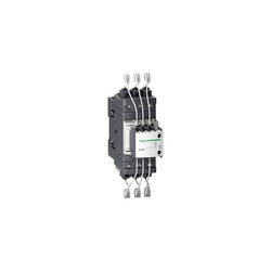
TeSys D contactor 3P 40A AC-3 up to 440V coil 48-130V AC/DC EverLink

TeSys F contactor, 4 poles (4NO), 275A/690V AC-1, for non-inductive load applications. Contactor with no coil to allow a later selection and installation (coil to be ordered separately), it provides bolt terminals for bars or cables with lugs. For high operating rates until 2400 cycles/hour and environments until 55°C, it procures high reliability and durability. It makes installation and maintenance easy thanks to a drawer for insertion of the selected coil and a large choice of add-on blocks and accessories (to be ordered separately). Multi standards certified (IEC, UL, CSA, CCC, EAC, Marine), Green Premium compliant (RoHS/REACh).
Main
| Characteristic | Value(s) |
|---|---|
| Range | TeSys |
| product name | TeSys F |
| Product or Component Type | Contactor |
| Device short name | LC1F |
| Contactor application | Resistive load |
| Utilisation category | AC-1 |
| Poles description | 4P |
| power pole contact composition | 4 NO |
| [Ue] rated operational voltage | <= 690 V AC 50/60 Hz <= 460 V DC |
| [Ie] rated operational current | 275 A 104 °F (40 °C)) <= 440 V AC-1 |
Complementary
| Characteristic | Value(s) |
|---|---|
| [Uc] control circuit voltage | 24...575 V AC 40...400 Hz with LX9 coil 24...460 V DC with LX4 coil 100...250 V AC 50/60 Hz with LXE coil 100...380 V DC with LXE coil |
| [Uimp] rated impulse withstand voltage | 8 kV |
| Overvoltage category | III |
| [Ith] conventional free air thermal current | 275 A (at 104 °F (40 °C)) |
| Irms rated making capacity | 1850 A conforming to IEC 60947-4-1 |
| Rated breaking capacity | 1480 A conforming to IEC 60947-4-1 |
| [Icw] rated short-time withstand current | 1500 A 104 °F (40 °C) - 10 s 920 A 104 °F (40 °C) - 30 s 740 A 104 °F (40 °C) - 1 min 500 A 104 °F (40 °C) - 3 min 400 A 104 °F (40 °C) - 10 min |
| Associated fuse rating | 315 A gG at <= 440 V |
| Average impedance | 0.33 mOhm - Ith 275 A 50 Hz |
| [Ui] rated insulation voltage | 1000 V IEC 60947-4-1 1500 V VDE 0110 group C |
| Power dissipation per pole | 25 W AC-1 |
| Control circuit voltage limits | Operational: 0.85...1.1 Uc AC 40...400 Hz with LX9 coil Drop-out: 0.2...0.55 Uc AC 40...400 Hz with LX9 coil Operational: 0.85...1.1 Uc DC with LX4 coil Drop-out: 0.15...0.2 Uc DC with LX4 coil Operational: 85...275 V AC 50/60 Hz with LXE coil Drop-out: 0...60 V AC 50/60 Hz with LXE coil Operational: 85...418 V DC with LXE coil Drop-out: 0...45 V DC with LXE coil |
| Heat dissipation | 8â¦9.8 W 2.2â¦2.5 W |
| Operating time | 35 ms closing with LX9 coil 130 ms opening with LX9 coil 30...40 ms closing with LX4 coil 30...50 ms opening with LX4 coil 40...80 ms closing with LXE coil 6...54 ms opening with LXE coil |
| Mounting Support | Plate |
| Standards | EN 60947-4-1 IEC 60947-1 EN 60947-1 JIS C8201-4-1 IEC 60947-4-1 |
| Product Certifications | ABS CSA DNV BV UL CB RMRoS LROS (Lloyds register of shipping) RINA UKCA |
| Connections - terminals | Power circuit bar 2 25 x 3 mm Power circuit lugs-ring terminals 1 0.2 in² (150 mm²) Power circuit connector 1 0.2 in² (150 mm²) Power circuit bolted connection Control circuit screw clamp terminals 1 0.002â¦0.006 in² (1â¦4 mm²)flexible without cable end Control circuit screw clamp terminals 2 0.002â¦0.006 in² (1â¦4 mm²)flexible with cable end Control circuit screw clamp terminals 1 0.002â¦0.006 in² (1â¦4 mm²)flexible with cable end Control circuit screw clamp terminals 2 0.002â¦0.004 in² (1â¦2.5 mm²)solid without cable end Control circuit screw clamp terminals 1 0.002â¦0.006 in² (1â¦4 mm²) Control circuit screw clamp terminals 2 0.002â¦0.006 in² (1â¦4 mm²) Control circuit screw clamp terminals 1.0 0.0003â¦0.004 in² (0.2â¦2.5 mm²)flexible without cable end Control circuit screw clamp terminals 1.0 0.0004â¦0.004 in² (0.25â¦2.5 mm²)flexible with cable end Control circuit screw clamp terminals 1.0 0.0003â¦0.004 in² (0.2â¦2.5 mm²)solid without cable end |
| Tightening torque | Power circuit 159.3 lbf.in (18 N.m) Control circuit 10.6 lbf.in (1.2 N.m) Control circuit 5.3 lbf.in (0.6 N.m) |
| Mechanical durability | 10 Mcycles |
| Inrush power in VA | 950â¦1180 VA, 40...400 Hz cos phi 0.9 (at 68 °F (20 °C))with LX9 coil 737â¦902 VA (at 68 °F (20 °C))with LX4 coil 280â¦310 VA, 50/60 Hz cos phi 0.5 (at 68 °F (20 °C))with LXE coil 270â¦320 VA (at 68 °F (20 °C))with LXE coil |
| Hold-in power consumption in VA | 8.9â¦10.9 VA, 40...400 Hz cos phi 0.9 (at 68 °F (20 °C))with LX9 coil 4.13â¦5.07 VA (at 68 °F (20 °C))with LX4 coil 4.5â¦7.0 VA, 50/60 Hz cos phi 0.5 (at 68 °F (20 °C))with LXE coil 2.5â¦4.0 VA (at 68 °F (20 °C))with LXE coil |
| Maximum operating rate | 2400 cyc/h 131 °F (55 °C) |
| Compatibility code | LC1F |
TeSys K contactor - 3P - AC-3 <= 440 V 9 A - 1 NC aux. - 110 V AC coil
EasyPact TVS contactor 3P(3 NO) - AC-3 -= 440 V 32A - 48 V AC coil

"TeSys Deca contactor, 3 poles (3NO), for motor control applications up to 9A/690V AC-3/3e (4kW@400V)." "and for non-inductive load control applications up to 25A@60â in category AC-1." "It provides a 400V 50/60Hz standard AC coil,1NO/1NC built-in auxiliary contact, connection by spring terminals." "For operating rates until 3600 cycles/hour and environments until 60°C, it procures reliability and durability to standard applications." "Compact (45mm width), DIN-rail mounting or screw fixing." "Multi standards certified (IEC, UL, CSA, CCC, EN), Green Premium compliant (RoHS/REACh)."
Main
| Characteristic | Value(s) |
|---|---|
| Range of product | TeSys Deca |
| Product or component type | Contactor |
| Device short name | LC1D |
| Contactor application | Motor control Resistive load |
| Utilisation category | AC-3 AC-1 AC-4 AC-3e |
| Poles description | 3P |
| [Ue] rated operational voltage | Power circuit: <= 690 V AC 25...400 Hz Power circuit: <= 300 V DC |
| [Ie] rated operational current | 9 A (at <60 °C) at <= 440 V AC AC-3 for power circuit 20 A (at <60 °C) at <= 440 V AC AC-1 for power circuit 9 A (at <60 °C) at <= 440 V AC AC-3e for power circuit |
| [Uc] control circuit voltage | 400 V AC 50/60 Hz |
Complementary
| Characteristic | Value(s) |
|---|---|
| Motor power kW | 2.2 kW at 220...230 V AC 50/60 Hz (AC-3) 4 kW at 380...400 V AC 50/60 Hz (AC-3) 4 kW at 415...440 V AC 50/60 Hz (AC-3) 5.5 kW at 500 V AC 50/60 Hz (AC-3) 5.5 kW at 660...690 V AC 50/60 Hz (AC-3) 2.2 kW at 400 V AC 50/60 Hz (AC-4) 2.2 kW at 220...230 V AC 50/60 Hz (AC-3e) 4 kW at 380...400 V AC 50/60 Hz (AC-3e) 4 kW at 415...440 V AC 50/60 Hz (AC-3e) 5.5 kW at 500 V AC 50/60 Hz (AC-3e) 5.5 kW at 660...690 V AC 50/60 Hz (AC-3e) |
| Motor power hp | 1 hp at 230/240 V AC 50/60 Hz for 1 phase motors 2 hp at 200/208 V AC 50/60 Hz for 3 phases motors 2 hp at 230/240 V AC 50/60 Hz for 3 phases motors 5 hp at 460/480 V AC 50/60 Hz for 3 phases motors 7.5 hp at 575/600 V AC 50/60 Hz for 3 phases motors 0.33 hp at 115 V AC 50/60 Hz for 1 phase motors |
| Compatibility code | LC1D |
| Pole contact composition | 3 NO |
| Protective cover | With |
| [Ith] conventional free air thermal current | 10 A (at 60 °C) for signalling circuit 16 A (at 60 °C) for power circuit |
| Irms rated making capacity | 250 A at 440 V for power circuit conforming to IEC 60947 140 A AC for signalling circuit conforming to IEC 60947-5-1 250 A DC for signalling circuit conforming to IEC 60947-5-1 |
| Rated breaking capacity | 250 A at 440 V for power circuit conforming to IEC 60947 |
| [Icw] rated short-time withstand current | 105 A 40 °C - 10 s for power circuit 210 A 40 °C - 1 s for power circuit 30 A 40 °C - 10 min for power circuit 61 A 40 °C - 1 min for power circuit 100 A - 1 s for signalling circuit 120 A - 500 ms for signalling circuit 140 A - 100 ms for signalling circuit |
| Associated fuse rating | 10 A gG for signalling circuit conforming to IEC 60947-5-1 25 A gG at <= 690 V coordination type 1 for power circuit 20 A gG at <= 690 V coordination type 2 for power circuit |
| Average impedance | 2.5 mOhm - Ith 16 A 50 Hz for power circuit |
| Power dissipation per pole | 1.56 W AC-1 0.2 W AC-3 0.2 W AC-3e |
| [Ui] rated insulation voltage | Power circuit: 690 V conforming to IEC 60947-4-1 Power circuit: 600 V CSA certified Power circuit: 600 V UL certified Signalling circuit: 690 V conforming to IEC 60947-1 Signalling circuit: 600 V CSA certified Signalling circuit: 600 V UL certified |
| Overvoltage category | III |
| pollution degree | 3 |
| [Uimp] rated impulse withstand voltage | 6 kV conforming to IEC 60947 |
| Safety reliability level | B10d = 1369863 cycles contactor with nominal load conforming to EN/ISO 13849-1 B10d = 20000000 cycles contactor with mechanical load conforming to EN/ISO 13849-1 |
| Mechanical durability | 15 Mcycles |
| Electrical durability | 0.6 Mcycles 25 A AC-1 at Ue <= 440 V 2 Mcycles 9 A AC-3 at Ue <= 440 V 2 Mcycles 9 A AC-3e at Ue <= 440 V |
| Control circuit type | AC at 50/60 Hz |
| Coil technology | Without built-in suppressor module |
| Control circuit voltage limits | 0.3...0.6 Uc (-40â¦70 °C):drop-out AC 50/60 Hz 0.8...1.1 Uc (-40â¦60 °C):operational AC 50 Hz 0.85...1.1 Uc (-40â¦60 °C):operational AC 60 Hz 1...1.1 Uc (60â¦70 °C):operational AC 50/60 Hz |
| Inrush power in VA | 70 VA 60 Hz cos phi 0.75 (at 20 °C) 70 VA 50 Hz cos phi 0.75 (at 20 °C) |
| Hold-in power consumption in VA | 7.5 VA 60 Hz cos phi 0.3 (at 20 °C) 7 VA 50 Hz cos phi 0.3 (at 20 °C) |
| Heat dissipation | 2â¦3 W at 50/60 Hz |
| Operating time | 12...22 ms closing 4...19 ms opening |
| Maximum operating rate | 3600 cyc/h at 60 °C |
| Connections - terminals | Power circuit: spring terminals 1 2.5 mm² - cable stiffness: flexible without cable end Power circuit: spring terminals 2 2.5 mm² - cable stiffness: flexible without cable end Control circuit: spring terminals 1 2.5 mm² - cable stiffness: flexible without cable end Control circuit: spring terminals 2 2.5 mm² - cable stiffness: flexible without cable end |
| Auxiliary contact composition | 1 NO + 1 NC |
| Auxiliary contacts type | type mechanically linked 1 NO + 1 NC conforming to IEC 60947-5-1 type mirror contact 1 NC conforming to IEC 60947-4-1 |
| Signalling circuit frequency | 25...400 Hz |
| Minimum switching voltage | 17 V for signalling circuit |
| Minimum switching current | 5 mA for signalling circuit |
| Insulation resistance | > 10 MOhm for signalling circuit |
| Non-overlap time | 1.5 ms on de-energisation between NC and NO contact 1.5 ms on energisation between NC and NO contact |
| Mounting support | Rail Plate |
TeSys D reversing contactor - 3P - <= 440 V - 12 A AC-3 - 48...130 V AC/DC coil
TeSys D contactor, 4 poles (2NO+2NC), for non-inductive load applications up to 25A/690V AC-1. It provides a 400V 50/60Hz AC coil, 1NO+1NC built-in auxiliary contacts (NC mirror certified), connection by screw clamp terminals. For operating rates until 3600 cycles/hour and environments until 60°C, it procures high reliability and durability. Compact (45mm width), DIN-rail mounting or screw fixing. Multi standards certified (IEC, UL, CSA, CCC, EAC, Marine), Green Premium compliant (RoHS/REACh).
Main
| Characteristic | Value(s) |
|---|---|
| Range | TeSys |
| Range of product | TeSys Deca |
| Product or component type | Contactor |
| Device short name | LC1D |
| Contactor application | Resistive load |
| Utilisation category | AC-1 |
| Poles description | 4P |
| [Ue] rated operational voltage | Power circuit: <= 690 V AC 25...400 Hz Power circuit: <= 300 V DC |
| [Ie] rated operational current | 25 A (at <60 °C) at <= 440 V AC AC-1 for power circuit |
| [Uc] control circuit voltage | 400 V AC 50/60 Hz |
Complementary
| Characteristic | Value(s) |
|---|---|
| Compatibility code | LC1D |
| Pole contact composition | 2 NO + 2 NC |
| Protective cover | With |
| [Ith] conventional free air thermal current | 25 A (at 60 °C) for power circuit 10 A (at 60 °C) for signalling circuit |
| Irms rated making capacity | 250 A at 440 V for power circuit conforming to IEC 60947 140 A AC for signalling circuit conforming to IEC 60947-5-1 250 A DC for signalling circuit conforming to IEC 60947-5-1 |
| Rated breaking capacity | 250 A at 440 V for power circuit conforming to IEC 60947 |
| [Icw] rated short-time withstand current | 105 A 40 °C - 10 s for power circuit 210 A 40 °C - 1 s for power circuit 30 A 40 °C - 10 min for power circuit 61 A 40 °C - 1 min for power circuit 100 A - 1 s for signalling circuit 120 A - 500 ms for signalling circuit 140 A - 100 ms for signalling circuit |
| Associated fuse rating | 10 A gG for signalling circuit conforming to IEC 60947-5-1 40 A gG at <= 690 V coordination type 1 for power circuit 25 A gG at <= 690 V coordination type 2 for power circuit |
| Average impedance | 2.5 mOhm - Ith 25 A 50 Hz for power circuit |
| Power dissipation per pole | 1.56 W AC-1 |
| [Ui] rated insulation voltage | Power circuit: 690 V conforming to IEC 60947-4-1 Power circuit: 600 V CSA certified Power circuit: 600 V UL certified Signalling circuit: 690 V conforming to IEC 60947-1 Signalling circuit: 600 V CSA certified Signalling circuit: 600 V UL certified |
| Overvoltage category | III |
| pollution degree | 3 |
| [Uimp] rated impulse withstand voltage | 6 kV conforming to IEC 60947 |
| Safety reliability level | B10d = 1369863 cycles contactor with nominal load conforming to EN/ISO 13849-1 B10d = 20000000 cycles contactor with mechanical load conforming to EN/ISO 13849-1 |
| Mechanical durability | 15 Mcycles |
| Electrical durability | 0.8 Mcycles 25 A AC-1 at Ue <= 440 V |
| Control circuit type | AC at 50/60 Hz |
| Coil technology | Without built-in suppressor module |
| Control circuit voltage limits | 0.3...0.6 Uc (-40â¦70 °C):drop-out AC 50/60 Hz 0.8...1.1 Uc (-40â¦60 °C):operational AC 50 Hz 0.85...1.1 Uc (-40â¦60 °C):operational AC 60 Hz 1...1.1 Uc (60â¦70 °C):operational AC 50/60 Hz |
| Inrush power in VA | 70 VA 60 Hz cos phi 0.75 (at 20 °C) 70 VA 50 Hz cos phi 0.75 (at 20 °C) |
| Hold-in power consumption in VA | 7.5 VA 60 Hz cos phi 0.3 (at 20 °C) 7 VA 50 Hz cos phi 0.3 (at 20 °C) |
| Heat dissipation | 2â¦3 W at 50/60 Hz |
| Operating time | 12...22 ms closing 4...19 ms opening |
| Maximum operating rate | 3600 cyc/h at 60 °C |
| Connections - terminals | Power circuit: screw clamp terminals 1 1â¦4 mm² - cable stiffness: flexible without cable end Power circuit: screw clamp terminals 2 1â¦4 mm² - cable stiffness: flexible without cable end Power circuit: screw clamp terminals 1 1â¦4 mm² - cable stiffness: flexible with cable end Power circuit: screw clamp terminals 2 1â¦2.5 mm² - cable stiffness: flexible with cable end Power circuit: screw clamp terminals 1 1â¦4 mm² - cable stiffness: solid without cable end Power circuit: screw clamp terminals 2 1â¦4 mm² - cable stiffness: solid without cable end Control circuit: screw clamp terminals 1 1â¦4 mm² - cable stiffness: flexible without cable end Control circuit: screw clamp terminals 2 1â¦4 mm² - cable stiffness: flexible without cable end Control circuit: screw clamp terminals 1 1â¦4 mm² - cable stiffness: flexible with cable end Control circuit: screw clamp terminals 2 1â¦2.5 mm² - cable stiffness: flexible with cable end Control circuit: screw clamp terminals 1 1â¦4 mm² - cable stiffness: solid without cable end Control circuit: screw clamp terminals 2 1â¦4 mm² - cable stiffness: solid without cable end |
| Tightening torque | Power circuit: 1.7 N.m - on screw clamp terminals - with screwdriver flat à 6 mm Power circuit: 1.7 N.m - on screw clamp terminals - with screwdriver Philips No 2 Control circuit: 1.7 N.m - on screw clamp terminals - with screwdriver flat à 6 mm Control circuit: 1.7 N.m - on screw clamp terminals - with screwdriver Philips No 2 |
| Auxiliary contact composition | 1 NO + 1 NC |
| Auxiliary contacts type | type mechanically linked 1 NO + 1 NC conforming to IEC 60947-5-1 type mirror contact 1 NC conforming to IEC 60947-4-1 |
| Signalling circuit frequency | 25...400 Hz |
| Minimum switching voltage | 17 V for signalling circuit |
| Minimum switching current | 5 mA for signalling circuit |
| Insulation resistance | > 10 MOhm for signalling circuit |
| Non-overlap time | 1.5 ms on de-energisation between NC and NO contact 1.5 ms on energisation between NC and NO contact |
| Mounting support | Plate Rail |
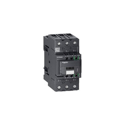
TeSys D reversing contactor - 3P(3 NO) - AC-3 - <= 440 V 18 A - 24 V DC coil
TeSys Deca contactor, 3 poles (3NO), for motor control applications up to 32A/440V AC-3/3e (15kW@400V). They can be used to create motor starters for almost any type of application. It provides a 400V 50/60Hz AC coil, 1NO+1NC built-in auxiliary contacts (NC mirror certified), connection by screw clamp terminals. For operating rates until 3600 cycles/hour and environments until 60°C, it procures high reliability and durability. Compact (45mm width), DIN-rail mounting or screw fixing. Contactor is rated for 7.5HP at 200 to 208VAC, 10HP at 240VAC, 20HP at 480VAC and 30HP at 600VAC three phase. Multi standards certified (IEC, UL, CSA, CCC, EAC, Marine). When used with a 480VAC up to 60A circuit breaker, this contactor can have a SCCR up to 85kA. When used with up to a 600VAC 80A Class J or CC fuse, this contactor can have a SCCR up to 100kA. Contactor is supplied with a 400 VAC 50/60 Hz coil. Contactor has one normally open and one normally closed auxiliary contact built-in as standard. The NC contact is mirror certified. Screw clamp terminals are used for load and auxiliary connections. An extensive line of accessories makes it easy to meet the requirements of most applications. The contactor is 3.35 inches tall, 1.77 inches wide and 3.62 inches deep. It weighs 0.83 lbs. Contactor is certified to UL, CSA, IEC, CCC, EAC and Marine standards.
Main
| Characteristic | Value(s) |
|---|---|
| Range | TeSys TeSys Deca |
| Range of Product | TeSys Deca |
| Product or Component Type | Contactor |
| Device short name | LC1D |
| Contactor application | Motor control Resistive load |
| Utilisation category | AC-4 AC-1 AC-3 AC-3e |
| Poles description | 3P |
| [Ue] rated operational voltage | Power circuit <= 690 V AC 25...400 Hz Power circuit <= 300 V DC |
| [Ie] rated operational current | 32 A (at <140 °F (60 °C)) at <= 440 V AC AC-3 for power circuit 50 A (at <140 °F (60 °C)) at <= 440 V AC AC-1 for power circuit 32 A (at <140 °F (60 °C)) at <= 440 V AC AC-3e for power circuit |
| [Uc] control circuit voltage | 400 V AC 50/60 Hz |
Complementary
| Characteristic | Value(s) |
|---|---|
| Motor power kW | 7.5 kW at 220...230 V AC 50/60 Hz (AC-3) 15 kW at 380...400 V AC 50/60 Hz (AC-3) 15 kW at 415...440 V AC 50/60 Hz (AC-3) 18.5 kW at 500 V AC 50/60 Hz (AC-3) 18.5 kW at 660...690 V AC 50/60 Hz (AC-3) 7.5 kW at 400 V AC 50/60 Hz (AC-4) 7.5 kW at 220...230 V AC 50/60 Hz (AC-3e) 15 kW at 380...400 V AC 50/60 Hz (AC-3e) 15 kW at 415...440 V AC 50/60 Hz (AC-3e) 18.5 kW at 500 V AC 50/60 Hz (AC-3e) 18.5 kW at 660...690 V AC 50/60 Hz (AC-3e) |
| Maximum Horse Power Rating | 2 hp at 115 V AC 50/60 Hz for 1 phase motors 5 hp at 230/240 V AC 50/60 Hz for 1 phase motors 10 hp at 200/208 V AC 50/60 Hz for 3 phase motors 10 hp at 230/240 V AC 50/60 Hz for 3 phase motors 20 hp at 460/480 V AC 50/60 Hz for 3 phase motors 25 hp at 575/600 V AC 50/60 Hz for 3 phase motors |
| Compatibility code | LC1D |
| Pole contact composition | 3 NO |
| Protective cover | With |
| [Ith] conventional free air thermal current | 10 A (at 140 °F (60 °C)) for signalling circuit 50 A (at 140 °F (60 °C)) for power circuit |
| Irms rated making capacity | 140 A AC for signalling circuit conforming to IEC 60947-5-1 250 A DC for signalling circuit conforming to IEC 60947-5-1 550 A at 440 V for power circuit conforming to IEC 60947 |
| Rated breaking capacity | 550 A at 440 V for power circuit conforming to IEC 60947 |
| [Icw] rated short-time withstand current | 60 A 104 °F (40 °C) - 10 min for power circuit 138 A 104 °F (40 °C) - 1 min for power circuit 260 A 104 °F (40 °C) - 10 s for power circuit 430 A 104 °F (40 °C) - 1 s for power circuit 100 A - 1 s for signalling circuit 120 A - 500 ms for signalling circuit 140 A - 100 ms for signalling circuit |
| Associated fuse rating | 10 A gG for signalling circuit conforming to IEC 60947-5-1 63 A gG at <= 690 V coordination type 1 for power circuit 63 A gG at <= 690 V coordination type 2 for power circuit |
| Average impedance | 2 mOhm - Ith 50 A 50 Hz for power circuit |
| Power dissipation per pole | 2 W AC-3 5 W AC-1 2 W AC-3e |
| [Ui] rated insulation voltage | Power circuit 600 V CSA Power circuit 600 V UL Signalling circuit 690 V IEC 60947-1 Signalling circuit 600 V CSA Signalling circuit 600 V UL Power circuit 690 V IEC 60947-4-1 |
| Overvoltage category | III |
| pollution degree | 3 |
| [Uimp] rated impulse withstand voltage | 6 kV IEC 60947 |
| Safety reliability level | B10d = 1369863 cycles contactor with nominal load EN/ISO 13849-1 B10d = 20000000 cycles contactor with mechanical load EN/ISO 13849-1 |
| Mechanical durability | 15 Mcycles |
| Electrical durability | 1.65 Mcycles 32 A AC-3 <= 440 V 1.4 Mcycles 50 A AC-1 <= 440 V 1.65 Mcycles 32 A AC-3e <= 440 V |
| Control circuit type | AC 50/60 Hz standard |
| Coil technology | Without built-in suppressor module |
| Control circuit voltage limits | 0.3...0.6 Uc (-40â¦158 °F (-40â¦70 °C)):drop-out AC 50/60 Hz 0.8...1.1 Uc (-40â¦140 °F (-40â¦60 °C)):operational AC 50 Hz 0.85...1.1 Uc (-40â¦140 °F (-40â¦60 °C)):operational AC 60 Hz 1...1.1 Uc (140â¦158 °F (60â¦70 °C)):operational AC 50/60 Hz |
| Inrush power in VA | 70 VA 60 Hz cos phi 0.75 (at 68 °F (20 °C)) 70 VA 50 Hz cos phi 0.75 (at 68 °F (20 °C)) |
| Hold-in power consumption in VA | 7.5 VA 60 Hz cos phi 0.3 (at 68 °F (20 °C)) 7 VA 50 Hz cos phi 0.3 (at 68 °F (20 °C)) |
| Heat dissipation | 2â¦3 W at 50/60 Hz |
| Operating time | 4...19 ms opening 12...22 ms closing |
| Maximum operating rate | 3600 cyc/h at 60 °C |
| Connections - terminals | Control circuit: screw clamp terminals 2 0.002â¦0.004 in² (1â¦2.5 mm²) - cable stiffness: flexible with cable end Control circuit: screw clamp terminals 1 0.002â¦0.006 in² (1â¦4 mm²) - cable stiffness: flexible without cable end Control circuit: screw clamp terminals 2 0.002â¦0.006 in² (1â¦4 mm²) - cable stiffness: flexible without cable end Control circuit: screw clamp terminals 1 0.002â¦0.006 in² (1â¦4 mm²) - cable stiffness: flexible with cable end Control circuit: screw clamp terminals 1 0.002â¦0.006 in² (1â¦4 mm²) - cable stiffness: solid without cable end Control circuit: screw clamp terminals 2 0.002â¦0.006 in² (1â¦4 mm²) - cable stiffness: solid without cable end Power circuit: screw clamp terminals 1 0.004â¦0.02 in² (2.5â¦10 mm²) - cable stiffness: flexible without cable end Power circuit: screw clamp terminals 2 0.004â¦0.02 in² (2.5â¦10 mm²) - cable stiffness: flexible without cable end Power circuit: screw clamp terminals 1 0.002â¦0.02 in² (1â¦10 mm²) - cable stiffness: flexible with cable end Power circuit: screw clamp terminals 2 0.002â¦0.009 in² (1.5â¦6 mm²) - cable stiffness: flexible with cable end Power circuit: screw clamp terminals 1 0.002â¦0.02 in² (1.5â¦10 mm²) - cable stiffness: solid without cable end Power circuit: screw clamp terminals 2 0.004â¦0.02 in² (2.5â¦10 mm²) - cable stiffness: solid without cable end |
| Tightening torque | Control circuit 15.05 lbf.in (1.7 N.m) screw clamp terminals flat à 6 mm Control circuit 15.05 lbf.in (1.7 N.m) screw clamp terminals Philips No 2 Power circuit 22.1 lbf.in (2.5 N.m) screw clamp terminals flat à 6 mm Power circuit 22.1 lbf.in (2.5 N.m) screw clamp terminals Philips No 2 Control circuit 15.05 lbf.in (1.7 N.m) screw clamp terminals pozidriv No 2 Power circuit 22.1 lbf.in (2.5 N.m) screw clamp terminals pozidriv No 2 |
| Auxiliary contact composition | 1 NO + 1 NC |
| Auxiliary contacts type | Mechanically linked 1 NO + 1 NC IEC 60947-5-1 Mirror contact 1 NC IEC 60947-4-1 |
| Signalling circuit frequency | 25...400 Hz |
| Minimum switching voltage | 17 V for signalling circuit |
| Minimum switching current | 5 mA for signalling circuit |
| Insulation resistance | > 10 MOhm for signalling circuit |
| Non-overlap time | 1.5 ms on de-energisation between NC and NO contact 1.5 ms on energisation between NC and NO contact |
| Mounting Support | Plate Rail |
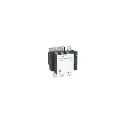
TeSys F contactor - 3P (3 NO) - AC-3 - <= 440 V 185 A - coil 230 V AC. Comes without coil.