
 1 year warranty


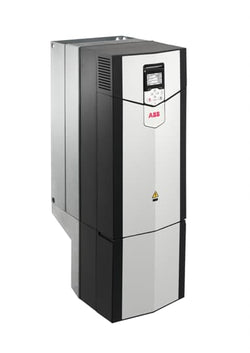
AC Drive, Voltage: Three-phase 380-500VAC. Power: 160 kW. Frame: R8. Degrees of Protection: IP21
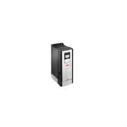
AC DRIVE, ACS880 SERIES, 3-PHASE, WALL MOUNTED, 156 AMP, 90 KW, 380-500 VAC, 50/60 HZ, FRAME SIZE R7

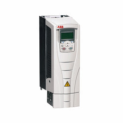
AC DRIVE, ACS880 SERIES, 3-PHASE, WALL MOUNTED, 96 AMP, 55 KW, 380-500 VAC, 50/60 HZ, FRAME SIZE R6
Drive, AC, 15HP, 480V, 21.0A, CT, N1 480Vin 3PH 20HP 27.0A VT W/DB Trans
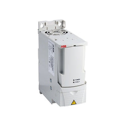
ACS550 IP21 5.5kW/7.5kW 400V 3ph AC Inverter Drive, HMI, DBr, C2 EMC

ACS355 4kW 400V 3ph AC Inverter Drive, STO, C3 EMC
ACS355 1.5kW 400V 3ph AC Inverter Drive, STO, C3 EMC

Altivar Soft Starter ATS480 is intended to start and stop asynchronous motors supplied from 208V to 690V. It meets the requirements of the most demanding applications in normal and heavy duty. With an operational rated current of 250A in normal duty, it supplies motor from 75kW to 250kW according to mains voltage. Designed for digitization, connected, optimized to meet cybersecurity standard, it simplifies project execution and maximizes the availability of applications. Its torque control (TCS) masters acceleration and deceleration. It efficiently stops high inertia application thanks to the dynamic braking and DC injection. It could be connected in-line or inside the delta to reduce its operational current. The embedded test routine simplifies the commissioning inside the delta. Its dimensions are 320mm (width) x 277mm (depth) x 380mm (height) and it weighs 18,2kg. Altivar Soft Starter ATS480 is designed to address process, infrastructures and industrial machines. It conforms to IEC/EN60947-4-1. It is certified CE, cULus, UKCA, CCC, RCM, EAC, and Marine certified DNV, ABS, BV and CCS. Display terminals, remote mounting kit, communication modules are common with Altivar Drives. Line chokes, DNV kits are common with ATS48. ATS480 is compatible with ATS48, it has same footprint, fixing, torque control algorithm, I/O, menus⦠The integration of Altivar Soft Starter ATS480 in EcoStruxure drastically simplifies architecture selection, detailed design and execution in automation and electrical systems.
Main
| Characteristic | Value(s) |
|---|---|
| Range of Product | Altivar Soft Starter ATS480 |
| Product or Component Type | Soft starter |
| Product destination | Asynchronous motors |
| Product Specific Application | Process and infrastructures |
| Device short name | ATS480 |
| Phase | 3 phase |
| Utilisation category | AC-3A AC-53A |
| Ue power supply voltage | 208...690 V - 15...10 % |
| power supply frequency | 50...60 Hz - 20...20 % |
| [Ie] rated operational current | Normal duty 250.0 A 104 °F (40 °C)) |
| rated current in heavy duty | 210.0 A at 104 °F (40 °C) heavy duty |
| Torque control | True |
| IP Degree of Protection | IP00 |
| Motor power kW | 75.0 kW 230 V in the motor supply line normal duty 55.0 kW 230 V in the motor supply line heavy duty 132.0 kW 400 V in the motor supply line normal duty 110.0 kW 400 V in the motor supply line heavy duty 132.0 kW 440 V in the motor supply line normal duty 110.0 kW 440 V in the motor supply line heavy duty 160.0 kW 500 V in the motor supply line normal duty 132.0 kW 500 V in the motor supply line heavy duty 160.0 kW 525 V in the motor supply line normal duty 132.0 kW 525 V in the motor supply line heavy duty 220.0 kW 660 V in the motor supply line normal duty 160.0 kW 660 V in the motor supply line heavy duty 250.0 kW 690 V in the motor supply line normal duty 200.0 kW 690 V in the motor supply line heavy duty 132.0 kW 230 V to the motor delta terminals normal duty 110.0 kW 230 V to the motor delta terminals heavy duty 220.0 kW 400 V to the motor delta terminals normal duty 160.0 kW 400 V to the motor delta terminals heavy duty |
| Maximum Horse Power Rating | 75.0 hp 208 V normal duty 60.0 hp 208 V heavy duty 100.0 hp 230 V normal duty 75.0 hp 230 V heavy duty 200.0 hp 460 V normal duty 150.0 hp 460 V heavy duty 250.0 hp 575 V normal duty 200.0 hp 575 V heavy duty |
| Option card | Communication module Profibus DP V1 Communication module Modbus TCP/EtherNet/IP Communication module CANopen daisy chain Communication module CANopen Sub-D Communication module CANopen open style Communication module PROFINET |
Complementary
| Characteristic | Value(s) |
|---|---|
| Device connection | In the motor supply line To the motor delta terminals |
| [Us] control circuit voltage | 110...230 V AC 50/60 Hz - 15...10 % |
| Apparent power | 0.106 kVA |
| Integrated motor overload protection | True |
| motor thermal protection class | Class 10E |
| Protection type | Phase failure line Integrated thermal protection motor Thermal protection starter Current overload motor Underload motor Excessive starting time, locked rotor motor Motor phase loss motor Line supply phase loss line Line supply phase loss motor Thermal protection motor |
| current limiting %In (5 x Ie maximum) | 150â¦700 % |
| [In] Rated current pwr loss specifctn | 250.0 A |
| Power loss static current independent | 25.0 W |
| Power loss per device current dependent | 675.0 W |
| Standards | IEC 60947-4-2 UL 60947-4-2 IEC 60664-1 |
| Product Certifications | CE cULus CCC UKCA RCM EAC DNV ABS BV CCS |
| Marking | CE CCC UKCA EAC RCM CULus |
| [Uc] control circuit voltage | 24 V DC |
| Discrete input number | 4 |
| Discrete input type | STOP) logic inputs, 3500 Ohm RUN) logic inputs, 3500 Ohm DI3) programmable as logic input, 3500 Ohm DI4) programmable as logic input, 3500 Ohm |
| Input compatibility | STOP discrete input level 1 PLC IEC 61131-2 RUN discrete input level 1 PLC IEC 61131-2 DI3 discrete input level 1 PLC IEC 61131-2 DI4 discrete input level 1 PLC IEC 61131-2 |
| Discrete input logic | Programmable digital input < 5 V |
| Relay output number | 3 |
| Relay output type | Relay outputs R1A 1 NO Relay outputs R1B 1 NO Relay outputs RIC NO/NC programmable |
| Minimum switching current | 100 mA 12 V DC relay outputs |
| Maximum switching current | Relay outputs 2 A 250 V AC Relay outputs 2 A 30 V DC Relay outputs |
| Discrete output number | 2 |
| Discrete output type | DQ1) programmable digital output <= 30 V DQ2) programmable digital output <= 30 V |
| Output compatibility | Open collector level 1 PLC IEC 65A-68 |
| Analogue input number | 1 |
| Analogue input type | AI1/PTC PTC/Pt 100 temperature probe PTC2 PTC/Pt 100 temperature probe PTC3 PTC/Pt 100 temperature probe |
| Analogue output number | 1 |
| Analogue output type | Current output AQ1 0...20 mA or 0...10 V 500 Ohm |
| Communication Port Protocol | Modbus serial |
| Connector Type | 1 RJ45 |
| Communication data link | Serial |
| Physical interface | 2-wire RS 485 |
| Transmission Rate | 1200...256000 bit/s |
| Transmission frame | RTU |
| Data format | 8 bits, configurable odd, even or no parity |
| Type of polarization | No impedance Modbus serial |
| Number of addresses | 0â¦227 Modbus serial |
| Method of access | Slave Modbus serial |
| Function Available | External bypass control Pre-heating Smoke extraction Multi-motor cascade Second motor set User management Ports and services hardening Security event logging Cybersecure firmware update Single direction |
| Display screen available | True |
| Operating position | Vertical +/- 10 degree |
| Height | 15.0 in (380.0 mm) |
| Width | 12.6 in (320.0 mm) |
| Depth | 10.9 in (277.0 mm) |
| Product Weight | 40.1 lb(US) (18.2 kg) |

VFD-MS300, 3HP 2.2KW 480V 5.5A H

The C2000 Plus Series features precise speed, torque and position control functions that are suitable for both sensor and sensorless synchronous / asynchronous motors. Features Include: Advanced Drive Controls For both synchronous and asynchronous motors | Dual rating design (heavy duty / super heavy duty) | Speed / torque / position control mode Versatile Drive Controls Built-in PLC function | Built-in brake unit | Supports various network protocols | Position control Environmental Adaptability Built-in DC reactor | Built-in EMC filter | 50˚C operating temperature Modular Design Hot pluggable LCD keypad | I/O extension cards | Various PG (encoder) feedback cards | Network cards for fieldbus modules | Removable fan Others Fast Response to Impact Load | A Drive for Permanent Magnet (PM) Motors | High-Performance Field-oriented Control | Auto Energy-Saving Operation | Deceleration Energy Backup (DEB) | Drive System Management Platform

Temperature Control Module DIN Rail 100 ~ 240VAC, 24VDC
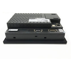
DOP-107EV - Delta, DOP-100 Series, 7″, Standard Panel, Ethernet

7” (800 * 480) 65536 Colors TFT Cortex-A8 800MHz CPU 256MB RAM 256MB ROM 1 COM port / 1 extension COM port USB Host USB Client CE/UL certified Operating temperature: 0°C – 50°C Storage temperature: -20°C - 60°C Number of keystrokes: > 10,000k times

ASD-A2-0721-U | DELTA | AC Servo Drive ASDA-A2 Series

Power distribution module - for I/O module 24 V DC & bus

Motor circuit breaker, TeSys GV2, 3P, 9-14 A, thermal magnetic, screw clamp terminals

Universal power supply, Phaseo, 1 or 2 phase, 100 to 500 V, 24 V, 5 A

This product is part of the Modicon X80 range, a common platform of modules for Modicon M580 and M340 Programmable Automation Controllers (PAC). This removable connection block is an accessory of programmable automation controllers. This product is robust, high quality and based on the latest innovative technology. It has 28 removable cage clamp terminals with 1 x 0.34mm² to 1mm² cross section. It weighs 0.111kg. It is suitable for medium to large process applications. This removable connection block is ideal for module with 28-pin removable terminal block. Modicon X80 consists in a compatible modules common platform that reduce maintenance and training costs with same spare parts in stock, and unique training for different Programmable Automation Controllers (PAC).
Main
| Characteristic | Value(s) |
|---|---|
| Range of Product | Modicon X80 |
| Accessory / Separate Part Type | Removable connection block |
| Number of terminals | 28 removable cage clamp terminal block |
| Accessory / separate part destination | For module with 28-pin removable terminal block |
Complementary
| Characteristic | Value(s) |
|---|---|
| Product Weight | 0.245 lb(US) (0.111 kg) |

The M340 processor module has a maximum of 1024 discrete and 256 analog I/O (Modbus or Ethernet). 36 application specific channels, product or component type. The processor module can do monitoring, diagnostic counters Modbus, event counters Modbus, is transparent ready, has 4 CANopen racks and 11 slots. It also has 1024 I/O multirack configuration, 704 I/O single rack configuration, analog I/O processor capacity, 256 I/O multirack configuration and 66 I/O single rack configuration. The Modicon M340 offers in a small form factor flexibility and integrated functions. In the heart of your process, it provides plug-and-play solutions with both Schneider Electric and third party devices. The large capacity of Unity Pro SoCollaborative software will ease and shorten programming and commissioning time. Modicon M340 Programmable Automation Controllers (PACs) are built to suit the needs of the process industry and a wide range of demanding automation applications. Modicon M340 PACs can be used individually, but are also the perfect companion to the Modicon M580. Together they can increase the performance, quality, and the profitability of your machine production. M340 PACs have an all in one CPU. It operates at 7 Kinst/ms. By using a multitasking system, it has reflex time. This PAC is programmed with Unity⢠Pro software. The M340 has a USB port for programming and HMI. Two additional Ethernet, CANopen® or Modbus⢠ports are available as required. The memory can process programming code up to 70 Kinst. Application back up is in a supplied memory card. Additional file storage is available up to 128 MB with FTP access. Additional file storage is available up to 128 MB with FTP access. The M340 range doesnât require a battery. It has extended temperature (-25°C +70°C) and conformal coating for operation in harsh environments. Protection for SI and OEM know how by using a SD card technology. Replace or hot swap I/O modules without stopping process. Configuration change on the fly (CCOTF) is used. No need to stop the process to expand system. FTD/DTM configuration tools for plug and play device integration. This simplifies configuration, commissioning, and maintenance. The M340 range is used in process industries, renewable energy applications (Solar, Wind power, etc.), water and cement applications, in manufacturing, in infrastructures and on machines.
Main
| Characteristic | Value(s) |
|---|---|
| Range of Product | Modicon X80 |
| Accessory / Separate Part Type | Removable connection block |
| Number of terminals | 20 removable screw clamp terminal block |
| Accessory / separate part destination | For module with 20-pin removable terminal block |
Complementary
| Characteristic | Value(s) |
|---|---|
| Product Weight | 0.165 lb(US) (0.075 kg) |

20-way removable cage clamp terminal block -1 x 0.34..1 mm2

A1000 series - AC Drive - 380Vac-480Vac - 72A/60A - 50HP - 3-phase input (3P)
Ordering
Popular Downloads
Dimensions
Technical
Technical UL/CSA
Environmental
Material Compliance
Certificates and Declarations
Container Information
External Classifications and Standards

Discrete output module M238 - 16 outputs relay- 1 removable screw terminal block

TeSys Deca contactor, 3 poles (3NO), for motor control applications up to 80A/1000V AC-3/AC-3e (37kW@400V). They can be used to create motor starters for almost any type of application. It provides a 24V DC coil, 1NO+1NC built-in auxiliary contacts (NC mirror certified), power connection by screw terminals, control connection by screw clamp terminals. For operating rates until 3600 cycles/hour and environments until 60°C, it procures high reliability and durability. Compact (85mm width), DIN-rail mounting or screw fixing. Contactor is rated for 25HP at 200 to 208VAC, 30HP at 240VAC, 60HP at 480VAC and 60HP at 600VAC three phase. Multi standards certified (IEC, UL, CSA, CCC, EAC, Marine). When used with a 480VAC up to 150A circuit breaker, this contactor can have a SCCR up to 100kA. When used with up to a 600VAC 175A Class J or CC fuse, this contactor can have a SCCR up to 100kA. Contactor is supplied with a 24 VDC coil with transient suppressor module. Contactor has one normally open and one normally closed auxiliary contact built-in as standard. The NC contact is mirror certified. Screw clamp terminals are used for load and auxiliary connections. An extensive line of accessories makes it easy to meet the requirements of most applications. The contactor is 5.00 inches tall, 3.35 inches wide and 7.32 inches deep. It weighs 5.71 lbs. Contactor is certified to UL, CSA, IEC, CCC, EAC and Marine standards.
Main
| Characteristic | Value(s) |
|---|---|
| Range | TeSys |
| Range of Product | TeSys Deca |
| Product or Component Type | Contactor |
| Device short name | LC1D |
| Contactor application | Motor control Resistive load |
| Utilisation category | AC-3 AC-3e AC-4 AC-1 |
| Poles description | 3P |
| [Ue] rated operational voltage | Power circuit <= 300 V DC 25...400 Hz Power circuit <= 690 V AC |
| [Ie] rated operational current | 125 A (at <140 °F (60 °C)) at <= 1000 V AC AC-1 for power circuit 80 A (at <140 °F (60 °C)) at <= 440 V AC AC-3 for power circuit 80 A (at <140 °F (60 °C)) at <= 440 V AC-3e for power circuit |
| [Uc] control circuit voltage | 24 V DC |
Complementary
| Characteristic | Value(s) |
|---|---|
| Motor power kW | 22 kW at 220...230 V AC 50 Hz (AC-3) 37 kW at 380...400 V AC 50 Hz (AC-3) 45 kW at 415...440 V AC 50 Hz (AC-3) 55 kW at 500 V AC 50 Hz (AC-3) 45 kW at 660...690 V AC 50 Hz (AC-3) 15 kW at 400 V AC 50 Hz (AC-4) 22 kW at 220...230 V AC 50 Hz (AC-3e) 37 kW at 380...400 V AC 50 Hz (AC-3e) 45 kW at 415...440 V AC 50 Hz (AC-3e) 55 kW at 500 V AC 50 Hz (AC-3e) 45 kW at 660...690 V AC 50 Hz (AC-3e) |
| Maximum Horse Power Rating | 7.5 hp at 120 V AC 50/60 Hz for 1 phase motors 15 hp at 230/240 V AC 50/60 Hz for 1 phase motors 30 hp at 200/208 V AC 50/60 Hz for 3 phase motors 30 hp at 230/240 V AC 50/60 Hz for 3 phase motors 60 hp at 460/480 V AC 50/60 Hz for 3 phase motors 60 hp at 575/600 V AC 50/60 Hz for 3 phase motors |
| Compatibility code | LC1D |
| Pole contact composition | 3 NO |
| Protective cover | With |
| [Ith] conventional free air thermal current | 10 A (at 140 °F (60 °C)) for signalling circuit 125 A (at 140 °F (60 °C)) for power circuit |
| Irms rated making capacity | 140 A AC for signalling circuit conforming to IEC 60947-5-1 250 A DC for signalling circuit conforming to IEC 60947-5-1 1100 A at 440 V for power circuit conforming to IEC 60947 |
| Rated breaking capacity | 1100 A at 440 V for power circuit conforming to IEC 60947 |
| [Icw] rated short-time withstand current | 640 A 104 °F (40 °C) - 10 s for power circuit 990 A 104 °F (40 °C) - 1 s for power circuit 135 A 104 °F (40 °C) - 10 min for power circuit 320 A 104 °F (40 °C) - 1 min for power circuit 100 A - 1 s for signalling circuit 120 A - 500 ms for signalling circuit 140 A - 100 ms for signalling circuit |
| Associated fuse rating | 10 A gG for signalling circuit conforming to IEC 60947-5-1 200 A gG at <= 690 V coordination type 1 for power circuit 160 A gG at <= 690 V coordination type 2 for power circuit |
| Average impedance | 0.8 mOhm - Ith 125 A 50 Hz for power circuit |
| Power dissipation per pole | 5.1 W AC-3 12.5 W AC-1 5.1 W AC-3e |
| [Ui] rated insulation voltage | Power circuit 600 V CSA Power circuit 600 V UL Power circuit 1000 V IEC 60947-4-1 Signalling circuit 690 V IEC 60947-1 Signalling circuit 600 V CSA Signalling circuit 600 V UL |
| Overvoltage category | III |
| pollution degree | 3 |
| [Uimp] rated impulse withstand voltage | 8 kV IEC 60947 |
| Safety reliability level | B10d = 1369863 cycles contactor with nominal load EN/ISO 13849-1 B10d = 20000000 cycles contactor with mechanical load EN/ISO 13849-1 |
| Mechanical durability | 4 Mcycles |
| Electrical durability | 0.8 Mcycles 125 A AC-1 <= 440 V 1.5 Mcycles 80 A AC-3 <= 440 V 1.5 Mcycles 80 A AC-3e <= 440 V |
| Control circuit type | DC standard |
| Coil technology | Without built-in suppressor module |
| Control circuit voltage limits | 0.1...0.3 Uc (-40â¦158 °F (-40â¦70 °C)):drop-out DC 0.85...1.1 Uc (-40â¦131 °F (-40â¦55 °C)):operational DC 1...1.1 Uc (131â¦158 °F (55â¦70 °C)):operational DC |
| Inrush power in W | 22 W 68 °F (20 °C)) |
| Hold-in power consumption in W | 22 W 68 °F (20 °C) |
| Operating time | 95...130 ms closing 20...35 ms opening |
| Time constant | 75 ms |
| Maximum operating rate | 3600 cyc/h at 60 °C |
| Connections - terminals | Control circuit: screw clamp terminals 2 0.002â¦0.004 in² (1â¦2.5 mm²) - cable stiffness: flexible with cable end Control circuit: screw clamp terminals 1 0.002â¦0.004 in² (1â¦2.5 mm²) - cable stiffness: flexible with cable end Control circuit: screw clamp terminals 1 0.002â¦0.006 in² (1â¦4 mm²) - cable stiffness: flexible without cable end Control circuit: screw clamp terminals 2 0.002â¦0.006 in² (1â¦4 mm²) - cable stiffness: flexible without cable end Control circuit: screw clamp terminals 1 0.002â¦0.006 in² (1â¦4 mm²) - cable stiffness: solid without cable end Control circuit: screw clamp terminals 2 0.002â¦0.006 in² (1â¦4 mm²) - cable stiffness: solid without cable end Power circuit: connector 1 0.006â¦0.08 in² (4â¦50 mm²) - cable stiffness: flexible without cable end Power circuit: connector 2 0.006â¦0.04 in² (4â¦25 mm²) - cable stiffness: flexible without cable end Power circuit: connector 1 0.006â¦0.08 in² (4â¦50 mm²) - cable stiffness: flexible with cable end Power circuit: connector 2 0.006â¦0.02 in² (4â¦16 mm²) - cable stiffness: flexible with cable end Power circuit: connector 1 0.006â¦0.08 in² (4â¦50 mm²) - cable stiffness: solid without cable end Power circuit: connector 2 0.006â¦0.04 in² (4â¦25 mm²) - cable stiffness: solid without cable end |
| Tightening torque | Control circuit 10.6 lbf.in (1.2 N.m) screw clamp terminals flat à 6 mm Control circuit 10.6 lbf.in (1.2 N.m) screw clamp terminals Philips No 2 Power circuit 106.2 lbf.in (12 N.m) connector flat à 6 to à 8 mm Power circuit 106.2 lbf.in (12 N.m) connector hexagonal 0.2 in (4 mm) Control circuit 10.6 lbf.in (1.2 N.m) screw clamp terminals pozidriv No 2 |
| Auxiliary contact composition | 1 NO + 1 NC |
| Auxiliary contacts type | Mechanically linked 1 NO + 1 NC IEC 60947-5-1 Mirror contact 1 NC IEC 60947-4-1 |
| Signalling circuit frequency | 25...400 Hz |
| Minimum switching voltage | 17 V for signalling circuit |
| Minimum switching current | 5 mA for signalling circuit |
| Insulation resistance | > 10 MOhm for signalling circuit |
| Non-overlap time | 1.5 ms on de-energisation between NC and NO contact 1.5 ms on energisation between NC and NO contact |
| Mounting Support | Plate Rail |