
 1 year warranty

Ordering
Popular Downloads
Dimensions
Technical
Technical UL/CSA
Environmental
Material Compliance
ABB EcoSolutions
Certificates and Declarations
Container Information
External Classifications and Standards

ABB EcoSolutions
Material Compliance
Environmental
Ordering
Dimensions
Container Information
Additional Information
Technical
Certificates and Declarations
External Classifications and Standards
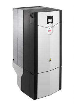
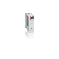
AC DRIVE, ACS880 SERIES, 3 PHASE, 380-500 VAC, 350 HP, 414 AMP, 250 KW, 6000 WATT, 50/60 HZ, IP21

ACS550 IP21 37kW/45kW 400V 3ph AC Inverter Drive, HMI, C2 EMC
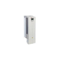
ACS550 IP21 22kW/30kW 400V 3ph AC Inverter Drive, HMI, C2 EMC

ACS550 IP21 15kW/18.5kW 400V 3ph AC Inverter Drive, HMI, C2 EMC
ACS550 IP21 11kW/15kW 400V 3ph AC Inverter Drive, HMI, C2 EMC
ACS550 IP21 3kW/4kW 400V 3ph AC Inverter Drivewith Braking, C2 EMC
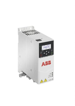
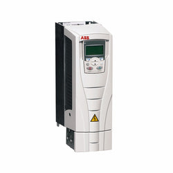
ACS380-040S-07A2-4 PN: 3kW, IN: 7.2A; The ACS380 machinery drive comes in several variants, ensuring seamless integration into machines and connecting perfectly to automation systems. It’s a great fit for industries such as food and beverage, material handling and textile. Typical applications include mixers, conveyors, EOT and tower cranes, extruders, and textile machinery. With the integrated functional safety features, the ACS380 drive can be also part of the machine’s safety system via PROFIsafe over PROFINET, ensuring the motor is safely stopped when required. In addition, the drive’s software can be easily customized with adaptive programming to match any specific application requirements.

ACS355 Inverter Drive, 3-Phase In, 0 to 600Hz Out, 22 kW, 400 V ac, 44 A

ACS355 3kW 400V 3ph AC Inverter Drive, STO, C3 EMC


Specifications
Model |
LR-ZB100CP |
|||
Type |
Distance based laser sensor |
|||
Appearance |
Rectangular |
|||
Output |
PNP |
|||
Cable connection |
M8 connector, 4-pin |
|||
Detectable distance |
35 to 100 mm 1.38" to 3.94" (650 to 0)*1 |
|||
Standard detectable deviation |
35 to 50 mm 1.38" to 1.97": 1.5 mm 0.06" |
|||
Display resolution |
2 (0.2 mm 0.008") |
|||
Spot size |
Approx. 2 × 1 mm 0.08" × 0.04" at 100 mm 3.94" |
|||
Response time |
1.5 ms / 10 ms / 50 ms selectable |
|||
Light source |
Type |
Red laser (660 nm) |
||
Laser class |
Class 1 laser product |
|||
Function |
Indicator |
3-digit 7-segment display (red), |
||
Timer |
OFF/ON delay/OFF delay/One-shot |
|||
Specifications |
Power voltage |
10 to 30 VDC, including 10% ripple (P-P), Class 2 or LPS |
||
Power consumption |
450 mW or less (18 mA or less at 24 V, 34 mA or less at 12 V) |
|||
Control output |
PNP Open collector, |
|||
Protection circuit |
Protection against reverse power connection, output overcurrent, output surge, reverse output connection |
|||
Output operation |
Light-ON / Dark-ON selectable |
|||
External input |
Input time calibration: 35 ms or more ON, 35 ms or more OFF |
|||
Environmental resistance |
Enclosure rating |
IP68 (IEC60529), IP69K (DIN40050-9), NEMA 4X, 6P, 13 (NEMA250), ECOLAB*3, Diversey*3 |
||
Insulation resistance |
20 MΩ or more (500 VDC) |
|||
Ambient light |
Incandescent lamp: 4,000 lux or less |
|||
Ambient temperature |
-10 to +50 °C 14 to 122 °F (No freezing) |
|||
Relative humidity |
35 to 85 % RH (No condensation) |
|||
Storage temperature |
-25 to +75 °C -13 to 167 °F (No freezing) |
|||
Withstand voltage |
1,000 VAC, 50/60 Hz, 1 min |
|||
Vibration resistance |
10 to 55 Hz, Double amplitude 1.5 mm 0.06", 2 hours in each of the X, Y, and Z directions |
|||
Shock resistance |
1,000 m/s2, 6 times in each of the X, Y, and Z directions |
|||
Material |
Case: SUS316L, Display: PES, Lens cover: PMMA with scratch-resistant coating, |
|||
Accompanying items |
Instruction Manual, |
|||
Weight |
Approx. 55 g |
|||
*1 Display readings can be used as a guide for the detecting distance. When the setting value is tuned, the readout shifts. When the value exceeds "-99", "-FF" is displayed. | ||||
Specifications
Model |
LR-W500C |
|||
Type |
M12 connector 4-pin type |
|||
Detecting distance |
30 to 500 mm 1.18" to 19.69" |
|||
Min. spot diameter |
Adjustable spot |
|||
Light source |
White LED |
|||
Mutual interference reduction function |
Up to 2 units when alternate frequencies set |
|||
Timer |
OFF/ON delay/OFF delay/One-shot |
|||
Response time |
200 µs/1 ms/10 ms/100 ms/500 ms selectable *1 |
|||
I/O |
Control output |
NPN open collector/PNP open collector selectable |
||
External input |
Tuning /Transmission OFF selectable |
|||
Protection circuit |
Protection against reverse power connection, power supply surge, output overcurrent, output surge, and reverse output connection |
|||
Power supply |
Power voltage |
10 to 30 VDC, including 10% ripple (P-P), Class 2 or LPS |
||
Current consumption |
65 mA or less (without load) at 24 VDC; |
|||
Environmental resistance |
Enclosure rating |
IP65/IP67 (IEC60529) |
||
Ambient light |
Incandescent lamp: 10,000 lux or less, Sunlight: 20,000 lux or less |
|||
Ambient temperature |
-20 to +50 °C -4 to 122 °F (No freezing) |
|||
Relative humidity |
35 to 85 % RH (No condensation) |
|||
Vibration resistance |
10 to 55 Hz, Double amplitude 1.5 mm 0.06", 2 hours in each of the X, Y, and Z directions |
|||
Shock resistance |
1,000 m/s2, 6 times in each of the X, Y, and Z directions |
|||
Material |
Case: Zinc die cast (Nickel chrome plating), |
|||
Weight |
Approx. 110 g |
|||
*1 When alternate frequencies are set, the response time increases by approximately 20%. | ||||

| Product | |
| Article Number (Market Facing Number) | 6ES75121SM030AB0 | 6ES75121SM030AB0 |
| Product Description | SIMATIC DP, CPU 1512SP F-1 PN for ET 200SP, central processing unit with 600 KB work memory for program and 2 MB for data, 1st interface: PROFINET IRT with 3-port switch, 6 ns bit performance, SIMATIC Memory Card required, BusAdapter required for port 1 and 2 |
| Product family | CPU 1512SP F-1 PN |
| Product Lifecycle (PLM) | PM300:Active Product |
| Additional Product Information | |
| EAN | 4047623412748 |
| UPC | 195125392700 |
| Commodity Code | 85371091 |
| LKZ_FDB/ CatalogID | ST76 |
| Product Group | 4A79 |
| Group Code | R152 |
| Country of origin | Germany |
| SCIP number | 5ee0de54-be70-442b-9211-3b11ee1d3534 |
| Delivery information | |
| Net Weight (lb) | 0.758 lb |
| Package size unit of measure | Inch |
| Packaging Quantity | 1 |
| Product | |
| Article Number (Market Facing Number) | 6ES71314BD010AA0 | 6ES71314BD010AA0 |
| Product Description | *** Spare part *** SIMATIC DP, 5 electronic modules for ET 200S, 4DI standard 24 V DC, 15 mm width, 5 units per packing unit |
| Product family | Not available |
| Product Lifecycle (PLM) | PM410:Product cancellation |
| Additional Product Information | |
| EAN | 4025515072287 |
| UPC | 662643216974 |
| Commodity Code | 85389091 |
| LKZ_FDB/ CatalogID | ST76 |
| Product Group | 4467 |
| Group Code | R151 |
| Country of origin | China |
| SCIP number | Not available |
| Delivery information | |
| Net Weight (lb) | 0.384 lb |
| Package size unit of measure | Inch |
| Packaging Quantity | 5 |

| Product | |
| Article Number (Market Facing Number) | 6AV21283GB060AX1 |
| Product Description | SIMATIC HMI MTP700, Unified Comfort Panel, touch operation, 7" widescreen TFT display, 16 million colors, PROFINET interface, configurable as of WinCC Unified Comfort V16, contains open-source software, which is provided free of charge see enclosed DVD |
| Product family | SIMATIC HMI Unified Comfort Panels Standard |
| Product Lifecycle (PLM) | PM300:Active Product |
| Additional Product Information | |
| EAN | 4047623411901 |
| UPC | 195125282056 |
| Commodity Code | 85371091 |
| LKZ_FDB/ CatalogID | ST80.1 |
| Product Group | X00F |
| Group Code | R141 |
| Country of origin | Germany |
| SCIP number | 237299bd-02e8-4694-bc16-45d88f0cffb1 |
| Delivery information | |
| Net Weight (lb) | 3.810 lb |
| Package size unit of measure | Inch |
| Packaging Quantity | 1 |

| Product | |
| Article Number (Market Facing Number) | 6AV21233KB320AW0 | 6AV21233KB320AW0 |
| Product Description | SIMATIC HMI MTP1000, Unified Basic Panel, touch operation, 10" widescreen TFT display, 16 million colors, PROFINET interface, configurable as of WinCC Unified Basic V18 Update 3, contains open-source software, which is provided free of charge see enclosed Blu-ray |
| Product family | SIMATIC HMI Unified Basic Panels |
| Product Lifecycle (PLM) | PM300:Active Product |
| Additional Product Information | |
| EAN | 4034106035204 |
| UPC | 195125450523 |
| Commodity Code | 85371091 |
| LKZ_FDB/ CatalogID | ST80.1 |
| Product Group | X0KS |
| Group Code | R141 |
| Country of origin | China |
| SCIP number | d5dcc9d1-c74a-4d61-b324-051a38fff612 |
| Delivery information | |
| Net Weight (lb) | 3.307 lb |
| Package size unit of measure | Inch |
| Packaging Quantity | 1 |

ABB EcoSolutions
Material Compliance
Environmental
Ordering
Dimensions
Container Information
Additional Information
Technical
Certificates and Declarations
External Classifications and Standards

PLC Direct is not an authorized distributor. We offer a broad range of in-stock products with minimal lead time.

PLC Direct is not an authorized distributor. We offer a broad range of in-stock products with minimal lead time.
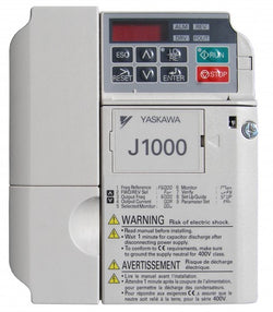
J DRIVE, 480V 3-PH, 5.4/4.8A
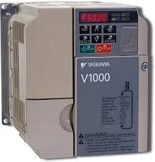
V DRIVE, 240V 3-PH, 19.6/17.5A, N1

Yaskawa GA50U4004ABA 480 Volt Three Phase 4.1 Amp 2 HP Microdrive