
 1 year warranty


DC digital input module - Mitsubishi Electric (MELSEC iQ-R Series) - 16I/O [16DI (16 x digital inputs (24Vdc; 0.1-70ms response))] - with screw-clamp term. connections - Backplane / rack mounting

Analog current input module - Mitsubishi Electric (MELSEC iQ-R Series) - 8I/O [8AI (8 x analog inputs (0-20mA / 4-20mA))] - with screw-clamp term. connections - Backplane / rack mounting

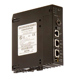
Programmable Logic Controller (PLC) CPU unit - Mitsubishi Electric (MELSEC iQ-R Series) - 80Ksteps / 320KBytes (Program) memory capacity - connection capacity 4096 x I/O points max - with USB2.0 connector - with Ethernet communication capability - Supply voltage 5Vdc (from dedicated iQ-R series P.S.U.) - Backplane / rack mounting

Servomotor Hg Series, Power 100 W; Torque 0.32 Nm, Max. Torque 1.1 Nm

Mitsubishi Q Series Input Module, Melsec Ans/Qnas Series Module, 24 V Dc, Din Rail Mount

Mitsubishi, A Series, Input/Output Module, 8 Input, 8 Output, 1.5 Ms, 118 X 50 X 40 Mm
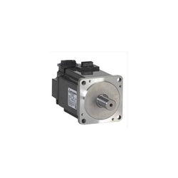
SERVO MOTOR 7.0KW 2KRPM W/KEY
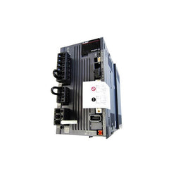
1-Axis Servo Amplifier, 2.0kw, 1000r/min, IP67
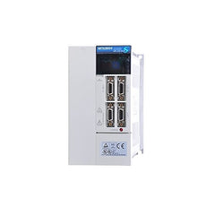
SERVO AMPLIFIER, 3.5 KW, SSCNET BUS CONTROL, 200-230 VAC, 3 PHASE, 16 AMP
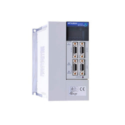
SERVO AC AMPLIFIER, 2000 W INPUT, 10.5 AMP, 200-230V / 50/60 HZ, 2 KW, SERVO AMPLIFIER (DIGITAL OR ANALOGUE CONTROL) (200 V 3-PHASE ONLY)
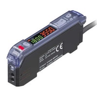
Specifications
Model |
FS-V31P |
|||
Type |
1-output with cable |
|||
Output |
PNP |
|||
Main unit/Expansion unit |
Main unit |
|||
Control output |
1 output |
|||
Monitor output (1 to 5 V) |
N/A |
|||
External input | ||||
Connector |
― |
|||
Light source LED |
Red, 4-element LED (Wavelength: 640 nm) |
|||
Response time |
33 µs (HIGH SPEED) /250 µs (FINE) /500 µs (TURBO) /1 ms (SUPER TURBO) /4 ms (ULTRA TURBO) /16 ms (MEGA TURBO) |
|||
Output selection |
LIGHT-ON/DARK-ON (switch-selectable) |
|||
Display indicator |
Operation indicator: Red LED/Dual digital monitor: Dual 7-segment display, Preset Value (4-digit green LED indicator) and |
|||
Size |
30.3 mm (H) x 9.8 mm (W) x 71.8 mm (D) 1.19" (H) x 0.39" (W) x 2.83" (D) |
|||
Detection mode |
Light intensity (area detection possible, automatic sensitivity-tracking function provided) |
|||
Timer function |
OFF-delay timer/ON-delay timer/One-shot timer/ON-delay timer + OFF-delay timer/ON-delay timer + One-shot timer, selectable |
|||
Control output |
PNP open-collector 24 V, 100 mA max.*1 (main unit only)/20 mA max. (when the expansion unit(s) is connected), Residual voltage: 1 V max. |
|||
External inputy |
Input time: 2 ms (ON)/20 ms (OFF) min.*2 |
|||
Unit expansion |
Up to 16 expansion units can be connected (a total of 17 units). Note that the 2-output type should be counted as two units. |
|||
Number of interference prevention units |
Normal operation |
HIGHSPEED:0 FINE:4 TURBO/SUPER/ULTRA/MEGA:8台 |
||
Rating |
Power voltage |
12 to 24 VDC ±10 %, Ripple (P-P) 10 % or less |
||
Power consumption |
Normal: 750 mW max. (Using 24 V, 31 mA max., using 12 V, 40 mA max.)/ |
|||
Environmental resistance |
Ambient light |
Incandescent lamp: 20,000 lux max., Sunlight: 30,000 lux max. |
||
Ambient temperature |
-10 to +55 °C 14 to 131 °F (No freezing)*4 |
|||
Relative humidity |
35 to 85 % RH (No condensation) |
|||
Vibration resistance |
10 to 55 Hz, Double amplitude 1.5 mm 0.06", 2 hours in each of the X, Y, and Z directions |
|||
Shock resistance |
500 m/s2, 3 times in each of the X, Y, and Z directions |
|||
Case material |
Polycarbonate |
|||
Accessories |
N/A |
|||
Weight |
Approx. 80 g |
|||
*1 Total current of two outputs should be less than 100 mA. | ||||

Specifications
Model |
FS-N41C*1 |
|||
Type |
M8 Connector*2 |
|||
Main unit/expansion unit |
Main unit |
|||
Response time |
23 µs (S-HSPD*3) /50 µs (HSPD*4) /250 µs (FINE) /500 µs (TURBO) /1 ms (SUPER) /4 ms (ULTRA) /16 ms (MEGA) /64 ms (TERA) |
|||
Number of control outputs |
2*5 |
|||
Number of external inputs |
1*5 |
|||
Light source LED |
Transmitter side: Red, four-element LED (wavelength: 660 nm) |
|||
Control output |
Open-collector, 30 V or less 100 mA or less per output, |
|||
External input |
Input time: 2 ms (ON) /20 ms (OFF) or longer*6 |
|||
Protection circuit |
Protection against reverse power connection, output overcurrent, output surge, and reverse output connection |
|||
Mutual interference prevention |
S-HSPD/HSPD: 0 units, FINE: 4 units, TURBO/SUPER/ULTRA/MEGA/TERA: 8 units (The mutual interference prevention values are twice those shown here when Double is set.) |
|||
Power supply |
Power voltage |
10 to 30 VDC (including 10 % ripple (P-P) or less) , class 2 or LPS*7 |
||
Power consumption |
During normal operation: 910 mW or less (36 mA or less at 24 V/65 mA or less at 12 V) |
|||
Environmental resistance |
Ambient light |
Incandescent lamp: 20,000 lx or less, sunlight: 30,000 lx or less |
||
Ambient temperature |
-20 °C -4 °F to +55 °C +131 °F (no freezing)*9 |
|||
Vibration resistance |
10 to 55 Hz; double amplitude 1.5 mm 0.06"; 2 hours each for X, Y, and Z axes |
|||
Shock resistance |
500 m/s2; 3 times each for X, Y, and Z axes |
|||
Case material |
Main unit and cover: polycarbonate |
|||
Weight |
Approx. 25 g |
|||
*1 IO-Link Specifi cation V.1.1/COM2 (38.4 kbps) is supported. | ||||
CPU 374 MODULE (240K BYTES CONFIGURABLE USER MEMORY), EMBEDDED ETHERNET 10/100MBS W/BUILT-IN SWITCH. NO SERIAL PORTS, WITHOUT BATTERY
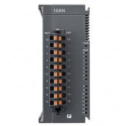
Basic I/O Module 16 Digital Outputs PNP 24Vdc for Delta AS/AX series. NEW

Programmable Logic Controller (PLC) Chassis Mount, DIN Rail 24VDC

Programmable Logic Controller (PLC) DIN Rail 24VDC

Programmable Logic Controller (PLC) Chassis Mount, DIN Rail 24VDC

PROGRAMMABLE LOGIC CTRL 8-4/6-2R

VFD-E, 3HP 460V, MICRO VECTOR DR

The C2000 Plus Series features precise speed, torque and position control functions that are suitable for both sensor and sensorless synchronous / asynchronous motors. 460 V – 3 Phase 132 kW – 175 HP – 260 A

The C2000 Plus Series features precise speed, torque and position control functions that are suitable for both sensor and sensorless synchronous / asynchronous motors. 460 V – 3 Phase 22 kW – 30 HP – 45 Amps

Delta’s VFD-EL-W series is the new generation compact vector control drive. Simple, delicate and durable design inherits Delta’s superior drive technology. Various essential functions are built-in as standard, including: Multi-step Operation; Torque Compensation; PID Control; Multi-Pump Control; Water Supply at Constant Pressure; Leakage Detection function and so on. 460 V – 3 Phase 0.75 KW – 1 HP – 2.5 A

Delta’s VFD-EL-W series is the new generation compact vector control drive. Simple, delicate and durable design inherits Delta’s superior drive technology. Various essential functions are built-in as standard, including: Multi-step Operation; Torque Compensation; PID Control; Multi-Pump Control; Water Supply at Constant Pressure; Leakage Detection function and so on. Features Include: Simple Speed Control Horizontal Movement Fixed Load Applications 230 V – 1 Phase 0.4 KW – 0.5 HP – 2.5 A

Bus Terminal, 2-channel analog output, voltage, ±10 V, 12 bit, differential