


Ask for quote
Main
| Characteristic | Value(s) |
|---|---|
| Range | TeSys |
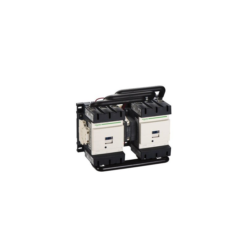
| product name | TeSys Deca |
| Product or Component Type | Reversing contactor |
| Device short name | LC2D |
| Contactor application | Resistive load Motor control |
| Utilisation category | AC-3 AC-1 AC-3e |
| Device presentation | Preassembled with reversing power busbar |
| Poles description | 3P |
| power pole contact composition | 3 NO |
| [Ue] rated operational voltage | Power circuit <= 1000 V AC 25...400 Hz Power circuit <= 300 V DC |
| [Ie] rated operational current | 200 A (at <140 °F (60 °C)) at <= 440 V AC AC-1 for power circuit 115 A (at <140 °F (60 °C)) at <= 440 V AC AC-3 for power circuit |
| Motor power kW | 30 kW at 220...230 V AC 50-60 Hz 55 kW at 380...400 V AC 50-60 Hz 59 kW at 415 V AC 50-60 Hz 59 kW at 440 V AC 50-60 Hz 75 kW at 500 V AC 50-60 Hz 80 kW at 660...690 V AC 50-60 Hz 65 kW at 1000 V AC 50-60 Hz |
| motor power HP (UL / CSA) | 30 hp at 200/208 V AC 60 Hz for 3 phase motors 40 hp at 230/240 V AC 60 Hz for 3 phase motors 75 hp at 460/480 V AC 60 Hz for 3 phase motors 100 hp at 575/600 V AC 60 Hz for 3 phase motors |
| Control circuit type | AC 50/60 Hz |
| [Uc] control circuit voltage | 115 V AC 50/60 Hz |
| Auxiliary contact composition | 1 NO + 1 NC |
| [Uimp] rated impulse withstand voltage | 8 kV IEC 60947 |
| Overvoltage category | III |
| [Ith] conventional free air thermal current | 200 A (at 140 °F (60 °C)) for power circuit |
| Irms rated making capacity | 140 A AC for signalling circuit conforming to IEC 60947-5-1 250 A DC for signalling circuit conforming to IEC 60947-5-1 1260 A at 440 V for power circuit conforming to IEC 60947 |
| Rated breaking capacity | 1100 A at 440 V for power circuit conforming to IEC 60947 |
| [Icw] rated short-time withstand current | 250 A 104 °F (40 °C) - 10 min for power circuit 550 A 104 °F (40 °C) - 1 min for power circuit 950 A 104 °F (40 °C) - 10 s for power circuit 1100 A 104 °F (40 °C) - 1 s for power circuit 100 A - 1 s for signalling circuit 120 A - 500 ms for signalling circuit 140 A - 100 ms for signalling circuit |
| Associated fuse rating | 10 A gG for signalling circuit conforming to IEC 60947-5-1 250 A gG at <= 690 V coordination type 1 for power circuit 200 A gG at <= 690 V coordination type 2 for power circuit |
| Average impedance | 0.6 mOhm - Ith 200 A 50 Hz for power circuit |
| [Ui] rated insulation voltage | Power circuit 600 V CSA Power circuit 600 V UL Signalling circuit 690 V IEC 60947-1 Signalling circuit 600 V CSA Signalling circuit 600 V UL Power circuit 1000 V IEC 60947-4-1 |
| Electrical durability | 0.8 Mcycles 200 A AC-1 <= 440 V 0.95 Mcycles 115 A AC-3 <= 440 V 0.95 Mcycles 115 A AC-3e <= 440 V |
| Power dissipation per pole | 24 W AC-1 7.9 W AC-3 7.9 W AC-3e |
| Front cover | With |
| Interlocking type | Mechanical Electrical |
| Mounting Support | Plate Rail |
| Standards | CSA C22.2 No 14 EN 60947-4-1 EN 60947-5-1 IEC 60947-4-1 IEC 60947-5-1 UL 508 |
| Product certifications | BV CCC CSA DNV GL RINA UL EAC UKCA |
| Connections - terminals | Control circuit screw clamp terminals 2 0.002â¦0.004 in² (1â¦2.5 mm²)flexible with cable end Control circuit screw clamp terminals 1 0.002â¦0.004 in² (1â¦2.5 mm²)flexible without cable end Control circuit screw clamp terminals 2 0.002â¦0.004 in² (1â¦2.5 mm²)flexible without cable end Control circuit screw clamp terminals 1 0.002â¦0.004 in² (1â¦2.5 mm²)flexible with cable end Control circuit screw clamp terminals 1 0.002â¦0.004 in² (1â¦2.5 mm²)solid without cable end Control circuit screw clamp terminals 2 0.002â¦0.004 in² (1â¦2.5 mm²)solid without cable end Power circuit connector 1 0.02â¦0.2 in² (10â¦120 mm²)flexible without cable end Power circuit connector 2 0.02â¦0.08 in² (10â¦50 mm²)flexible without cable end Power circuit connector 1 0.02â¦0.2 in² (10â¦120 mm²)flexible with cable end Power circuit connector 2 0.02â¦0.08 in² (10â¦50 mm²)flexible with cable end Power circuit connector 1 0.02â¦0.2 in² (10â¦120 mm²)solid without cable end Power circuit connector 2 0.02â¦0.08 in² (10â¦50 mm²)solid without cable end |
| Tightening torque | Control circuit 10.6 lbf.in (1.2 N.m) screw clamp terminals flat à 6 mm Control circuit 10.6 lbf.in (1.2 N.m) screw clamp terminals Philips No 2 Power circuit 106.2 lbf.in (12 N.m) connector hexagonal 0.2 in (4 mm) Control circuit 10.6 lbf.in (1.2 N.m) screw clamp terminals pozidriv No 2 |
| Operating time | 20...50 ms closing 6...20 ms opening |
| Safety reliability level | B10d = 1369863 cycles contactor with nominal load EN/ISO 13849-1 B10d = 20000000 cycles contactor with mechanical load EN/ISO 13849-1 |
| Mechanical durability | 8000000 cycles |
| Maximum operating rate | 2400 cyc/h 140 °F (60 °C) |
Complementary
| Characteristic | Value(s) |
|---|---|
| Coil technology | Built-in bidirectional peak limiting diode suppressor |
| Control circuit voltage limits | 0.3...0.5 Uc (131 °F (55 °C)):drop-out AC 50/60 Hz 0.8...1.15 Uc (131 °F (55 °C)):operational AC 50/60 Hz |
| Inrush power in VA | 280â¦350 VA 60 Hz 0.8 68 °F (20 °C)) 280â¦350 VA 50 Hz 0.8 68 °F (20 °C)) |
| Hold-in power consumption in VA | 2â¦18 VA 68 °F (20 °C)) 0.3 60 Hz 2â¦18 VA 68 °F (20 °C)) 0.3 50 Hz |
| Heat dissipation | 3â¦8 W 50/60 Hz |
| Auxiliary contacts type | Mechanically linked 1 NO + 1 NC IEC 60947-5-1 Mirror contact 1 NC IEC 60947-4-1 |
| Signalling circuit frequency | 25...400 Hz |
| Minimum switching current | 5 mA for signalling circuit |
| Minimum switching voltage | 17 V for signalling circuit |
| Non-overlap time | 1.5 ms on de-energisation between NC and NO contact 1.5 ms on energisation between NC and NO contact |
| Insulation resistance | > 10 MOhm for signalling circuit |
All PLC Direct products come with a 1-year warranty. The warranty is issued by PLC Direct. Warranty coverage commences at the date of purchase. The warranty is for mechanical defects or failures not caused by human factors including but not limited to (a) incorrect installation, (b) operating the unit in sub-optimal conditions or in scenarios not recommended by the manufacturer, (c) poor unit maintenance, etc. The warranty does not cover programming or software related issues.
If the product is eligible for PLC Direct’s warranty coverage and the customer encounters an issue with the product, we will request the item is shipped to us for diagnosis and examination. Regardless of the cause of product issues, the customer will bear responsibility for the cost of shipping the unit to PLC Direct for evaluation. Where the unit was damaged by human factors, we will offer a repair or replace quote; in cases where damage was caused by human factors, the customer is responsible for the cost of shipping the repaired/replaced unit from PLC Direct to the customer. Where the unit was not damaged by human factors but is covered by PLC Direct’s warranty, we will repair or replace the unit at our cost (or, in rare cases, refund you your purchase); in such cases, PLC Direct will bear the cost of shipping the repaired or replaced product back to the customer. It is up to PLC Direct’s discretion whether to repair, replace, or refund the customer in such cases. Diagnoses can take time to complete based on technician availability and the complexity of diagnosis.
In no event shall PLC Direct be liable for any damages except actual damages up to, but not exceeding, the amount paid to us for the product, including we shall not be liable for any consequential or indirect damages or lost profits whether or not advised of same.
PLC Direct offers free shipping worldwide. Product ship from a various warehouses worldwide based on the customer's and the product's location. The estimated delivery date on the product page is PLC Direct's best estimated assuming a US-based shipping destination.
Regardless of where the product is shipping from, PLC Direct covers all duties for US-based shipping destinations. For non-US-based shipping destinations, customers are responsible for duties as appropriate.
PLC Direct's focus is on balancing price with lead time. Some but not all products can be expedited. If you have questions about delivery ETAs, please contact our team.
Ask for quote
Trusted By


"Fast service for obsolete parts"
Increasingly PLC/ HMI control platforms are becoming obsolete and parts are no longer supported, however PLC Direct had the HMI we needed and fast shipping for our system to get back online!
Buyer at GE Health

"Helping us move projects forward"
With supply chain issues increasingly affecting our business, PLC Direct has been there for us to supply the PLC products we need, when we need it. If they don't have it readily available, they find it and provide it quickly and reliably. This has helped us move forward with several projects that would have otherwise taken us many, many months to complete.
Buyer at E-Merge Systems – A Rockwell Integrator