
 1 year warranty


Material Compliance
Environmental
Ordering
Dimensions
Container Information
Additional Information
Technical
Certificates and Declarations
External Classifications and Standards

Material Compliance
Environmental
Ordering
Dimensions
Container Information
Additional Information
Technical
Certificates and Declarations
External Classifications and Standards

ABB EcoSolutions
Material Compliance
Environmental
Ordering
Dimensions
Container Information
Additional Information
Technical
Certificates and Declarations
External Classifications and Standards

Material Compliance
Environmental
Ordering
Dimensions
Container Information
Additional Information
Technical
Certificates and Declarations
External Classifications and Standards

ABB EcoSolutions
Material Compliance
Popular Downloads
Environmental
Ordering
Dimensions
Container Information
Technical
Technical UL/CSA
Certificates and Declarations
External Classifications and Standards
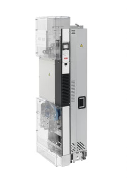
LV AC industrial single drive module, IEC: Pn 315 kW, 330 A, 690 V, UL: Pld 350 Hp, 336 A, 600 V (ACS880-04-330A-7)
Ordering
Popular Downloads
Dimensions
Technical
Technical UL/CSA
Environmental
Material Compliance
ABB EcoSolutions
Certificates and Declarations
Container Information
External Classifications and Standards
Ordering
Popular Downloads
Dimensions
Technical
Technical UL/CSA
Environmental
Material Compliance
ABB EcoSolutions
Certificates and Declarations
Container Information
External Classifications and Standards

Inverter Drive, 1-Phase In, 130Hz Out 0.37 kW, 230 V, 2.2 A ACS55, IP20

Accessory for safety PLC: Gate-P2 Gateway Profibus

Drive Control unit+cables RDCU-12C+cables. ACS800-04M-0550-5+E202+E208+H360+J400+K458+P901+P916+P920+OR715

Ordering
Popular Downloads
Dimensions
Technical
Technical UL/CSA
Environmental
Material Compliance
Certificates and Declarations
Container Information
External Classifications and Standards
Ordering
Popular Downloads
Dimensions
Technical
Technical UL/CSA
Environmental
Material Compliance
Certificates and Declarations
Container Information
External Classifications and Standards
Ordering
Popular Downloads
Dimensions
Technical
Technical UL/CSA
Environmental
Material Compliance
Certificates and Declarations
Container Information
External Classifications and Standards
Ordering
Popular Downloads
Dimensions
Technical
Technical UL/CSA
Environmental
Material Compliance
Certificates and Declarations
Container Information
External Classifications and Standards
Ordering
Popular Downloads
Dimensions
Technical
Technical UL/CSA
Environmental
Material Compliance
Certificates and Declarations
Container Information
External Classifications and Standards


ACS150 1.1kW 400V 3ph AC Inverter Drive, DBr, C3 EMC

ACS150 0.75kW 400V 3ph AC Inverter Drive, DBr, C3 EMC
ACS580 IP21 22kW/30kW 400V 3ph AC Inverter, HMI, STO, C2 EMC

ACS580 IP21 11kW/15kW 400V 3ph AC Inverter, HMI, DBr, STO, C2 EMC

AC Inverter for 2.2kW (3HP) 400V 3 Ph motor to 5.6A at high overload or 3kW (4HP) to 6.8A when Fan/Pump rated.

ACS580 IP21 1.1kW/1.5kW 400V 3ph AC Inverter, HMI, DBr, STO, C2 EMC.