
 1 year warranty


TeSys Deca control relay, 5 contacts (5NO), 10A/690V, for control of electromagnetic loads AC-15/DC-13. It provides a 24V DC control circuit with no inrush consumption and equipped with a surge suppression device, connection by screw clamp terminals. For high operating rates until 180 cycles/min and ambient temperature -40/+60°C, it procures high reliability and durability. Compact (45mm width), for clipping on 35mm DIN rail or fixing by screw. Multi standards certified (IEC, UL, CSA, CCC, EAC, Marine).
Main
| Characteristic | Value(s) |
|---|---|
| Range | TeSys TeSys Deca |
| product name | TeSys CAD |
| Product or Component Type | Control relay |
| Device short name | CAD |
| Contactor application | Control circuit |
Complementary
| Characteristic | Value(s) |
|---|---|
| Utilisation category | AC-14 DC-13 AC-15 |
| Pole contact composition | 5 NO |
| [Ue] rated operational voltage | <= 690 V AC 25...400 Hz |
| Control circuit type | DC standard |
| [Uc] control circuit voltage | 24 V DC |
| [Uimp] rated impulse withstand voltage | 6 kV IEC 60947 |
| [Ith] conventional free air thermal current | 10 A (at 140 °F (60 °C)) |
| Irms rated making capacity | 140 A AC IEC 60947-5-1 250 A DC IEC 60947-5-1 |
| [Icw] rated short-time withstand current | 100 A - 1 s 120 A - 500 ms 140 A - 100 ms |
| Associated fuse rating | 10 A gG conforming to IEC 60947-5-1 |
| [Ui] rated insulation voltage | 600 V UL 600 V CSA 690 V IEC 60947-5-1 |
| Mounting Support | Rail Plate |
| Connections - terminals | screw clamp terminals 1 0.002â¦0.006 in² (1â¦4 mm²)flexible without cable end screw clamp terminals 2 0.002â¦0.006 in² (1â¦4 mm²)flexible without cable end screw clamp terminals 1 0.002â¦0.006 in² (1â¦4 mm²)flexible with cable end screw clamp terminals 2 0.002â¦0.004 in² (1â¦2.5 mm²)flexible with cable end screw clamp terminals 1 0.002â¦0.006 in² (1â¦4 mm²)solid without cable end screw clamp terminals 2 0.002â¦0.006 in² (1â¦4 mm²)solid without cable end |
| Tightening torque | 10.6 lbf.in (1.2 N.m) screw clamp terminals Philips No 2 10.6 lbf.in (1.2 N.m) screw clamp terminals flat à 6 mm 10.6 lbf.in (1.2 N.m) screw clamp terminals pozidriv No 2 |
| Control circuit voltage limits | 0.1...0.25 Uc (-40â¦158 °F (-40â¦70 °C)):drop-out DC 0.7...1.25 Uc (-40â¦140 °F (-40â¦60 °C)):operational DC 1...1.25 Uc (140â¦158 °F (60â¦70 °C)):operational DC |
| Operating time | 53...72 ms coil energisation and NO closing 16...24 ms coil de-energisation and NO opening |
| Mechanical durability | 30 Mcycles |
| Maximum operating rate | 180 cyc/mn |
| Time constant | 28 ms |
| Inrush power in W | 5.4 W 68 °F (20 °C)) |
| Hold-in power consumption in W | 5.4 W 68 °F (20 °C) |
| Minimum switching voltage | 17 V |
| Minimum switching current | 5 mA |
| Non-overlap time | 1.5 ms on energisation between NC and NO contact 1.5 ms on de-energisation between NC and NO contact |
| Insulation resistance | > 10 MOhm |
| Mechanical robustness | Shocks control relay open10 Gn for 11 ms IEC 60068-2-27 Shocks control relay closed15 Gn for 11 ms IEC 60068-2-27 Vibrations control relay open2 Gn, 5...300 Hz IEC 60068-2-6 Vibrations control relay closed4 Gn, 5...300 Hz IEC 60068-2-6 |
| Height | 3.03 in (77 mm) |
| Width | 1.8 in (45 mm) |
| Depth | 3.7 in (93 mm) |
| Product Weight | 1.28 lb(US) (0.58 kg) |

TeSys U standard control unit to be inserted in power bases LUB12, LUB32, LUB38 to form a TeSys U starter controller, for 3-phase motor applications up to 1.5kW@400V. It provides full protection to motors with a rated current Ir 1.25-5A (Ir adjustable), overload tripping class 10, short circuit at 13 x Irmax, overcurrent at 14.2 x Ir, phase loss, insulation fault (protection of equipment only). To be used with a 24V AC voltage for the control of the starter (through the control terminals A1/A2 located in the power base). Certified when used in conjunction with a LUB power base (IEC, UL, CSA, CCC, EAC, Marine).
Main
| Characteristic | Value(s) |
|---|---|
| Range | TeSys |
| Range of Product | TeSys Ultra |
| product name | TeSys Ultra |
| Device short name | LUCA |
| Product or Component Type | Standard control unit |
| Device Application | Motor control Motor protection |
| Product Specific Application | Basic protection requirements for motor starters: overload and short-circuit |
| main function available | Manual reset Protection against overload and short-circuit Earth fault protection Protection against phase failure and phase imbalance |
| Product compatibility | Power base LUB12 Power base LUB32 Power base LUB38 Power base LUB120 Power base LUB320 Power base LUB380 Reversing contactor breaker LU2B12B Reversing contactor breaker LU2B32B |
| [Ue] rated operational voltage | 690 V AC |
| Network frequency | 40...60 Hz |
| Load type | 3-phase motor self-cooled |
| Utilisation category | AC-43 AC-41 AC-44 |
| Motor power kW | 1.5 kW 400...440 V AC 50/60 Hz 2.2 kW 500 V AC 50/60 Hz 3 kW 690 V AC 50/60 Hz |
| rated motor current adjustment range | 1.25â¦5 A |
| Thermal overload class | Class 10 40â¦60 Hz -13â¦158 °F (-25â¦70 °C) IEC 60947-6-2 Class 10 40â¦60 Hz -13â¦158 °F (-25â¦70 °C) UL 508 |
| Tripping threshold | 14.2 x Ir +/- 20 % |
| Phase failure sensitivity | Yes |
| [Uc] control circuit voltage | 24 V AC |
Complementary
| Characteristic | Value(s) |
|---|---|
| Control circuit voltage limits | 20...26.5 V AC 24 V in operation 14.5 V AC 24 V drop-out |
| Typical current consumption | 140 mA 24 V AC I maximum while closing with LUB12 220 mA 24 V AC I maximum while closing with LUB32 220 mA 24 V AC I maximum while closing with LUB38 70 mA 24 V AC I rms sealed with LUB12 90 mA 24 V AC I rms sealed with LUB32 90 mA 24 V AC I rms sealed with LUB38 |
| Heat dissipation | 2 W control circuit with LUB12 3 W control circuit with LUB32 3 W control circuit with LUB38 |
| Operating time | 35 ms opening with LUB12 control circuit 35 ms opening with LUB32 control circuit 35 ms opening with LUB38 control circuit 70 ms closing with LUB12 control circuit 70 ms closing with LUB32 control circuit 70 ms closing with LUB38 control circuit |
| Standards | EN 60947-6-2 IEC 60947-6-2 UL 60947-4-1, with phase barrier CSA C22.2 No 60947-4-1, with phase barrier |
| Product Certifications | CE UL CSA CCC EAC ASEFA ATEX Marine |
| [Ui] rated insulation voltage | 690 V IEC 60947-6-2 600 V UL 60947-4-1 600 V CSA C22.2 No 60947-4-1 |
| [Uimp] rated impulse withstand voltage | 6 kV IEC 60947-6-2 |
| Safe separation of circuit | 400 V SELV between the control and auxiliary circuits IEC 60947-1 400 V SELV between the control or auxiliary circuit and the main circuit IEC 60947-1 |
| Fixing mode | Plug-in (front face) |
| Width | 1.8 in (45 mm) |
| Height | 2.6 in (66 mm) |
| Depth | 2.4 in (60 mm) |
| Product Weight | 0.298 lb(US) (0.135 kg) |
| Compatibility code | LUCA |

Main
| Characteristic | Value(s) |
|---|---|
| Range of Product | Harmony Relay |
| Relay Type | Current measurement relay |
| Product or Component Type | Industrial measurement and control relays |
| Relay name | RM4J |
| Relay monitored parameters | Overcurrent or undercurrent detection |
| time delay | Adjustable 0.05...30 s |
| Maximum power consumption in VA | 3.3 VA AC |
| Measurement range | 1...5 A current AC 1...5 A current DC 3...15 A current AC 3...15 A current DC 300...1500 mA current AC 300...1500 mA current DC |
| Contacts type and composition | 2 C/O |
Complementary
| Characteristic | Value(s) |
|---|---|
| Maximum switching voltage | 440 V AC |
| operating voltage tolerance | 0.85...1.1 Uc |
| Maximum power consumption in W | 1.2 W DC |
| Output contacts | 2 C/O |
| Maximum measuring cycle | 80 ms |
| Internal input resistance | 0.06 Ohm 0.006 Ohm 0.02 Ohm |
| Permissible continuous overload | 7 A 20 A 2 A |
| Permissible non repetitive overload | 10 A <= 3 s 100 A 15 A |
| Setting accuracy of the switching threshold | +/-5 % |
| Switching threshold drift | <= 0.06 % per degree centigrade depending permissible ambient air temperature <= 0.5 % within the supply voltage range (0.85...1.1 Un) |
| Setting accuracy of time delay | 10 P |
| Time delay drift | <= 0.07 % per degree centigrade depending on temperature <= 0.5 % within the supply voltage range (0.85...1.1 Un) |
| Hysteresis | 5â¦30 % adjustable current threshold setting |
| Marking | CE : EMC 89/336/EEC CE : LVD 73/23/EEC |
| Overvoltage category | III conforming to IEC 60664-1 |
| [Ui] rated insulation voltage | 500 V IEC |
| Supply disconnection value | > 0.1 Uc |
| Operating position | Any position without derating |
| Connections - terminals | Screw terminals, 2 x 1.5 mm²flexible with cable end Screw terminals, 2 x 2.5 mm²flexible without cable end |
| Tightening torque | 5.3â¦9.7 lbf.in (0.6â¦1.1 N.m) |
| Mechanical durability | 30000000 cycles |
| [Ith] conventional free air thermal current | 8 A |
| [Ie] rated operational current | 2 A 24 V DC-13 158 °F (70 °C) IEC 60947-5-1/1991 2 A 24 V DC-13 158 °F (70 °C) VDE 0660 3 A 115 V AC-15 158 °F (70 °C) IEC 60947-5-1/1991 3 A 115 V AC-15 158 °F (70 °C) VDE 0660 3 A 24 V AC-15 158 °F (70 °C) IEC 60947-5-1/1991 3 A 24 V AC-15 158 °F (70 °C) VDE 0660 3 A 250 V AC-15 158 °F (70 °C) IEC 60947-5-1/1991 3 A 250 V AC-15 158 °F (70 °C) VDE 0660 0.1 A 250 V DC-13 158 °F (70 °C) IEC 60947-5-1/1991 0.1 A 250 V DC-13 158 °F (70 °C) VDE 0660 0.3 A 115 V DC-13 158 °F (70 °C) IEC 60947-5-1/1991 0.3 A 115 V DC-13 158 °F (70 °C) VDE 0660 |
| Switching capacity in mA | 10 mA 12 V |
| Switching voltage | 250 V AC |
| Contacts material | 90/10 silver nickel contacts |
| Number of cables | 2 |
| Width | 1.8 in (45 mm) |
| Depth | 3.1 in (80 mm) |
| Terminals description ISO n°1 | (C-B1-B2-B3)CO (25-26-28)OC (A1-A2)CO (15-16-18)OC |
| Output relay state | Tripped if V measured > V set Tripped if A measured > A set |
| 9 mm pitches | 5 |
| Product Weight | 0.450 lb(US) (0.204 kg) |

Main
| Characteristic | Value(s) |
|---|---|
| Range of Product | Altivar |
| Product or Component Type | Variable speed drive |
| Product Specific Application | Simple machine |
| Component name | ATV31 |
| Assembly style | With heat sink |
| Variant | With drive order potentiometer |
| EMC filter | Integrated |
| [Us] rated supply voltage | 380...500 V - 5...5 % |
| Supply frequency | 50...60 Hz - 5...5 % |
| Phase | 3 phase |
| Motor power kW | 1.1 kW 4 kHz |
| Maximum Horse Power Rating | 1.5 hp 4 kHz |
| Line current | 3.7 A 500 V 4.9 A 380 V, Isc = 1 kA |
| Apparent power | 3.2 kVA |
| Prospective line Isc | 1 kA |
| Nominal output current | 3 A 4 kHz |
| Maximum transient current | 4.5 A 60 s |
| Power dissipation in W | 48 W at nominal load |
| Asynchronous motor control profile | Factory set : constant torque Sensorless flux vector control with PWM type motor control signal |
| Analogue input number | 4 |
Complementary
| Characteristic | Value(s) |
|---|---|
| Product destination | Asynchronous motors |
| Supply voltage limits | 323â¦550 V |
| Network Frequency | 47.5...63 Hz |
| Output frequency | 0.0005â¦0.5 kHz |
| Nominal switching frequency | 4 kHz |
| Switching frequency | 2...16 kHz adjustable |
| Speed range | 1â¦50 |
| Transient overtorque | 150â¦170 % of nominal motor torque |
| Braking torque | <= 150 % 60 s with braking resistor 100 % with braking resistor continuously 150 % without braking resistor |
| Regulation loop | Frequency PI regulator |
| Motor slip compensation | Automatic whatever the load Suppressable Adjustable |
| Output voltage | <= power supply voltage |
| Electrical connection | Al1, Al2, Al3, AOV, AOC, R1A, R1B, R1C, R2A, R2B, LI1...LI6 terminal 0.004 in² (2.5 mm²) AWG 14 L1, L2, L3, U, V, W, PA, PB, PA/+, PC/- terminal 0.004 in² (2.5 mm²) AWG 14 |
| Tightening torque | Al1, Al2, Al3, AOV, AOC, R1A, R1B, R1C, R2A, R2B, LI1...LI6 5.3 lbf.in (0.6 N.m) L1, L2, L3, U, V, W, PA, PB, PA/+, PC/- 7.08 lbf.in (0.8 N.m) |
| Insulation | Electrical between power and control |
| Supply | Internal supply for logic inputs 19...30 V 100 mA overload and short-circuit protection Internal supply for reference potentiometer (2.2 to 10 kOhm) 10...10.8 V 10 mA overload and short-circuit protection |
| Analogue input type | AI3 configurable current 0...20 mA 250 Ohm AI1 configurable voltage 0...10 V 30 V max 30000 Ohm AI2 configurable voltage +/- 10 V 30 V max 30000 Ohm AIP potentiometer reference 8 ms 10 bits +/- 4.3 % +/- 0.2 % |
| Sampling duration | LI1...LI6 4 ms discrete AI1, AI2, AI3 8 ms analog |
| Response time | AOV, AOC 8 ms analog R1A, R1B, R1C, R2A, R2B 8 ms discrete |
| Linearity error | +/- 0.2 % output |
| Analogue output number | 2 |
| Analogue output type | AOC configurable current 0...20 mA 800 Ohm 8 bits AOV configurable voltage 0...10 V 470 Ohm 8 bits |
| Discrete input logic | Positive logic (source) LI1...LI6), < 5 V, > 11 V Logic input not wired LI1...LI4), < 13 V Negative logic (source) LI1...LI6), > 19 V |
| Discrete output number | 2 |
| Discrete output type | Configurable relay logic R1A, R1B, R1C) 1 NO + 1 NC - 100000 cycles Configurable relay logic R2A, R2B) NC - 100000 cycles |
| Minimum switching current | R1-R2 10 mA 5 V DC |
| Maximum switching current | R1-R2 2 A 250 V AC inductive, cos phi = 0.4 7 ms R1-R2 2 A 30 V DC inductive, cos phi = 0.4 7 ms R1-R2 5 A 250 V AC resistive, cos phi = 1 0 ms R1-R2 5 A 30 V DC resistive, cos phi = 1 0 ms |
| Discrete input number | 6 |
| Discrete input type | LI1...LI6) programmable 24 V, 0â¦100 mA PLC 3500 Ohm |
| Acceleration and deceleration ramps | Linear adjustable separately from 0.1 to 999.9 s S, U or customized |
| Braking to standstill | By DC injection |
| Protection type | Input phase breaks drive Line supply overvoltage and undervoltage safety circuits drive Line supply phase loss safety function, for three phases supply drive Motor phase breaks drive Overcurrent between output phases and earth (on power up only) drive Overheating protection drive Short-circuit between motor phases drive Thermal protection motor |
| Insulation resistance | >= 500 mOhm 500 V DC for 1 minute |
| Display type | 1 LED Red)drive voltage Four 7-segment display unitsCANopen bus status |
| Time constant | 5 ms for reference change |
| Frequency resolution | Display unit 0.1 Hz Analog input 0.1...100 Hz |
| Connector type | 1 RJ45 CANopen via VW3 CANTAP2 adaptor 1 RJ45 Modbus |
| Physical interface | RS485 multidrop serial link CANopen via VW3 CANTAP2 adaptor RS485 multidrop serial link Modbus |
| Transmission frame | RTU CANopen via VW3 CANTAP2 adaptor RTU Modbus |
| Transmission Rate | 10, 20, 50, 125, 250, 500 kbps or 1 Mbps CANopen via VW3 CANTAP2 adaptor 4800, 9600 or 19200 bps Modbus |
| Number of addresses | 1â¦127 CANopen via VW3 CANTAP2 adaptor 1â¦247 Modbus |
| Number of drive | 127 CANopen via VW3 CANTAP2 adaptor 31 Modbus |
| Marking | CE |
| Operating position | Vertical +/- 10 degree |
| Product Weight | 4.0 lb(US) (1.8 kg) |

Main
| Characteristic | Value(s) |
|---|---|
| Range of Product | Altivar |
| Product or Component Type | Variable speed drive |
| Product Specific Application | Simple machine |
| Component name | ATV31 |
| Assembly style | With heat sink |
| Variant | With drive order potentiometer |
| EMC filter | Integrated |
| [Us] rated supply voltage | 380...500 V - 5...5 % |
| Supply frequency | 50...60 Hz - 5...5 % |
| Phase | 3 phase |
| Motor power kW | 3 kW 4 kHz |
| Line current | 10.9 A 380 V, Isc = 1 kA 8.3 A 500 V |
| Apparent power | 7.1 kVA |
| Prospective line Isc | 1 kA |
| Nominal output current | 7.1 A 4 kHz |
| Maximum transient current | 10.7 A 60 s |
| Power dissipation in W | 125 W at nominal load |
| Asynchronous motor control profile | Factory set : constant torque Sensorless flux vector control with PWM type motor control signal |
| Analogue input number | 4 |
Complementary
| Characteristic | Value(s) |
|---|---|
| Product destination | Asynchronous motors |
| Supply voltage limits | 323â¦550 V |
| Network Frequency | 47.5...63 Hz |
| Output frequency | 0.0005â¦0.5 kHz |
| Nominal switching frequency | 4 kHz |
| Switching frequency | 2...16 kHz adjustable |
| Speed range | 1â¦50 |
| Transient overtorque | 150â¦170 % of nominal motor torque |
| Braking torque | <= 150 % 60 s with braking resistor 100 % with braking resistor continuously 150 % without braking resistor |
| Regulation loop | Frequency PI regulator |
| Motor slip compensation | Automatic whatever the load Adjustable Suppressable |
| Output voltage | <= power supply voltage |
| Electrical connection | Al1, Al2, Al3, AOV, AOC, R1A, R1B, R1C, R2A, R2B, LI1...LI6 terminal 0.004 in² (2.5 mm²) AWG 14 L1, L2, L3, U, V, W, PA, PB, PA/+, PC/- terminal 0.004 in² (2.5 mm²) AWG 14 |
| Tightening torque | Al1, Al2, Al3, AOV, AOC, R1A, R1B, R1C, R2A, R2B, LI1...LI6 5.3 lbf.in (0.6 N.m) L1, L2, L3, U, V, W, PA, PB, PA/+, PC/- 7.08 lbf.in (0.8 N.m) |
| Insulation | Electrical between power and control |
| Supply | Internal supply for logic inputs 19...30 V 100 mA overload and short-circuit protection Internal supply for reference potentiometer (2.2 to 10 kOhm) 10...10.8 V 10 mA overload and short-circuit protection |
| Analogue input type | AI3 configurable current 0...20 mA 250 Ohm AI1 configurable voltage 0...10 V 30 V max 30000 Ohm AI2 configurable voltage +/- 10 V 30 V max 30000 Ohm AIP potentiometer reference 8 ms 10 bits +/- 4.3 % +/- 0.2 % |
| Sampling duration | LI1...LI6 4 ms discrete AI1, AI2, AI3 8 ms analog |
| Response time | AOV, AOC 8 ms analog R1A, R1B, R1C, R2A, R2B 8 ms discrete |
| Linearity error | +/- 0.2 % output |
| Analogue output number | 2 |
| Analogue output type | AOC configurable current 0...20 mA 800 Ohm 8 bits AOV configurable voltage 0...10 V 470 Ohm 8 bits |
| Discrete input logic | Positive logic (source) LI1...LI6), < 5 V, > 11 V Logic input not wired LI1...LI4), < 13 V Negative logic (source) LI1...LI6), > 19 V |
| Discrete output number | 2 |
| Discrete output type | Configurable relay logic R1A, R1B, R1C) 1 NO + 1 NC - 100000 cycles Configurable relay logic R2A, R2B) NC - 100000 cycles |
| Minimum switching current | R1-R2 10 mA 5 V DC |
| Maximum switching current | R1-R2 2 A 250 V AC inductive, cos phi = 0.4 7 ms R1-R2 2 A 30 V DC inductive, cos phi = 0.4 7 ms R1-R2 5 A 250 V AC resistive, cos phi = 1 0 ms R1-R2 5 A 30 V DC resistive, cos phi = 1 0 ms |
| Discrete input number | 6 |
| Discrete input type | LI1...LI6) programmable 24 V, 0â¦100 mA PLC 3500 Ohm |
| Acceleration and deceleration ramps | Linear adjustable separately from 0.1 to 999.9 s S, U or customized |
| Braking to standstill | By DC injection |
| Protection type | Input phase breaks drive Line supply overvoltage and undervoltage safety circuits drive Line supply phase loss safety function, for three phases supply drive Motor phase breaks drive Overcurrent between output phases and earth (on power up only) drive Overheating protection drive Short-circuit between motor phases drive Thermal protection motor |
| Insulation resistance | >= 500 mOhm 500 V DC for 1 minute |
| Display type | 1 LED Red)drive voltage Four 7-segment display unitsCANopen bus status |
| Time constant | 5 ms for reference change |
| Frequency resolution | Display unit 0.1 Hz Analog input 0.1...100 Hz |
| Connector type | 1 RJ45 CANopen via VW3 CANTAP2 adaptor 1 RJ45 Modbus |
| Physical interface | RS485 multidrop serial link CANopen via VW3 CANTAP2 adaptor RS485 multidrop serial link Modbus |
| Transmission frame | RTU CANopen via VW3 CANTAP2 adaptor RTU Modbus |
| Transmission Rate | 10, 20, 50, 125, 250, 500 kbps or 1 Mbps CANopen via VW3 CANTAP2 adaptor 4800, 9600 or 19200 bps Modbus |
| Number of addresses | 1â¦127 CANopen via VW3 CANTAP2 adaptor 1â¦247 Modbus |
| Number of drive | 127 CANopen via VW3 CANTAP2 adaptor 31 Modbus |
| Marking | CE |
| Operating position | Vertical +/- 10 degree |
| Product Weight | 6.8 lb(US) (3.1 kg) |

Main
| Characteristic | Value(s) |
|---|---|
| Range of Product | Altivar |
| Product or Component Type | Variable speed drive |
| Product Specific Application | Simple machine |
| Component name | ATV31 |
| Assembly style | With heat sink |
| EMC filter | Integrated |
| [Us] rated supply voltage | 380...500 V - 5...5 % |
| Supply frequency | 50...60 Hz - 5...5 % |
| Phase | 3 phase |
| Motor power kW | 4 kW 4 kHz |
| Maximum Horse Power Rating | 5 hp 4 kHz |
| Line current | 10.6 A 500 V 13.9 A 380 V, Isc = 1 kA |
| Apparent power | 9.2 kVA |
| Prospective line Isc | 1 kA |
| Nominal output current | 9.5 A 4 kHz |
| Maximum transient current | 14.3 A 60 s |
| Power dissipation in W | 150 W at nominal load |
| Asynchronous motor control profile | Sensorless flux vector control with PWM type motor control signal Factory set : constant torque |
| Analogue input number | 3 |
Complementary
| Characteristic | Value(s) |
|---|---|
| Product destination | Asynchronous motors |
| Supply voltage limits | 323â¦550 V |
| Network Frequency | 47.5...63 Hz |
| Output frequency | 0.0005â¦0.5 kHz |
| Nominal switching frequency | 4 kHz |
| Switching frequency | 2...16 kHz adjustable |
| Speed range | 1â¦50 |
| Transient overtorque | 150â¦170 % of nominal motor torque |
| Braking torque | <= 150 % 60 s with braking resistor 100 % with braking resistor continuously 150 % without braking resistor |
| Regulation loop | Frequency PI regulator |
| Motor slip compensation | Suppressable Automatic whatever the load Adjustable |
| Output voltage | <= power supply voltage |
| Electrical connection | Al1, Al2, Al3, AOV, AOC, R1A, R1B, R1C, R2A, R2B, LI1...LI6 terminal 0.004 in² (2.5 mm²) AWG 14 L1, L2, L3, U, V, W, PA, PB, PA/+, PC/- terminal 0.004 in² (2.5 mm²) AWG 14 |
| Tightening torque | Al1, Al2, Al3, AOV, AOC, R1A, R1B, R1C, R2A, R2B, LI1...LI6 5.3 lbf.in (0.6 N.m) L1, L2, L3, U, V, W, PA, PB, PA/+, PC/- 7.08 lbf.in (0.8 N.m) |
| Insulation | Electrical between power and control |
| Supply | Internal supply for logic inputs 19...30 V 100 mA overload and short-circuit protection Internal supply for reference potentiometer (2.2 to 10 kOhm) 10...10.8 V 10 mA overload and short-circuit protection |
| Analogue input type | AI3 configurable current 0...20 mA 250 Ohm AI1 configurable voltage 0...10 V 30 V max 30000 Ohm AI2 configurable voltage +/- 10 V 30 V max 30000 Ohm |
| Sampling duration | LI1...LI6 4 ms discrete AI1, AI2, AI3 8 ms analog |
| Response time | AOV, AOC 8 ms analog R1A, R1B, R1C, R2A, R2B 8 ms discrete |
| Linearity error | +/- 0.2 % output |
| Analogue output number | 2 |
| Analogue output type | AOC configurable current 0...20 mA 800 Ohm 8 bits AOV configurable voltage 0...10 V 470 Ohm 8 bits |
| Discrete input logic | Positive logic (source) LI1...LI6), < 5 V, > 11 V Logic input not wired LI1...LI4), < 13 V Negative logic (source) LI1...LI6), > 19 V |
| Discrete output number | 2 |
| Discrete output type | Configurable relay logic R1A, R1B, R1C) 1 NO + 1 NC - 100000 cycles Configurable relay logic R2A, R2B) NC - 100000 cycles |
| Minimum switching current | R1-R2 10 mA 5 V DC |
| Maximum switching current | R1-R2 2 A 250 V AC inductive, cos phi = 0.4 7 ms R1-R2 2 A 30 V DC inductive, cos phi = 0.4 7 ms R1-R2 5 A 250 V AC resistive, cos phi = 1 0 ms R1-R2 5 A 30 V DC resistive, cos phi = 1 0 ms |
| Discrete input number | 6 |
| Discrete input type | LI1...LI6) programmable 24 V, 0â¦100 mA PLC 3500 Ohm |
| Acceleration and deceleration ramps | Linear adjustable separately from 0.1 to 999.9 s S, U or customized |
| Braking to standstill | By DC injection |
| Protection type | Input phase breaks drive Line supply overvoltage and undervoltage safety circuits drive Line supply phase loss safety function, for three phases supply drive Motor phase breaks drive Overcurrent between output phases and earth (on power up only) drive Overheating protection drive Short-circuit between motor phases drive Thermal protection motor |
| Insulation resistance | >= 500 mOhm 500 V DC for 1 minute |
| Display type | 1 LED Red)drive voltage Four 7-segment display unitsCANopen bus status |
| Time constant | 5 ms for reference change |
| Frequency resolution | Display unit 0.1 Hz Analog input 0.1...100 Hz |
| Connector type | 1 RJ45 CANopen via VW3 CANTAP2 adaptor 1 RJ45 Modbus |
| Physical interface | RS485 multidrop serial link CANopen via VW3 CANTAP2 adaptor RS485 multidrop serial link Modbus |
| Transmission frame | RTU CANopen via VW3 CANTAP2 adaptor RTU Modbus |
| Transmission Rate | 10, 20, 50, 125, 250, 500 kbps or 1 Mbps CANopen via VW3 CANTAP2 adaptor 4800, 9600 or 19200 bps Modbus |
| Number of addresses | 1â¦127 CANopen via VW3 CANTAP2 adaptor 1â¦247 Modbus |
| Number of drive | 127 CANopen via VW3 CANTAP2 adaptor 31 Modbus |
| Marking | CE |
| Operating position | Vertical +/- 10 degree |
| Outer dimension | 184 x 140 x 150 mm 402 x 239 x 192 mm 215 x 185 x 158 mm |
| Product Weight | 6.8 lb(US) (3.1 kg) |

Main
| Characteristic | Value(s) |
|---|---|
| Range of Product | Altivar |
| Product or Component Type | Variable speed drive |
| Product Specific Application | Simple machine |
| Component name | ATV31 |
| Assembly style | With heat sink |
| Variant | With drive order potentiometer |
| EMC filter | Integrated |
| [Us] rated supply voltage | 380...500 V - 5...5 % |
| Supply frequency | 50...60 Hz - 5...5 % |
| Phase | 3 phase |
| Motor power kW | 0.75 kW 4 kHz |
| Maximum Horse Power Rating | 1 hp 4 kHz |
| Line current | 2.7 A 500 V 3.6 A 380 V, Isc = 1 kA |
| Apparent power | 2.4 kVA |
| Prospective line Isc | 1 kA |
| Nominal output current | 2.3 A 4 kHz |
| Maximum transient current | 3.5 A 60 s |
| Power dissipation in W | 41 W at nominal load |
| Asynchronous motor control profile | Factory set : constant torque Sensorless flux vector control with PWM type motor control signal |
| Analogue input number | 4 |
Complementary
| Characteristic | Value(s) |
|---|---|
| Product destination | Asynchronous motors |
| Supply voltage limits | 323â¦550 V |
| Network Frequency | 47.5...63 Hz |
| Output frequency | 0.0005â¦0.5 kHz |
| Nominal switching frequency | 4 kHz |
| Switching frequency | 2...16 kHz adjustable |
| Speed range | 1â¦50 |
| Transient overtorque | 150â¦170 % of nominal motor torque |
| Braking torque | <= 150 % 60 s with braking resistor 100 % with braking resistor continuously 150 % without braking resistor |
| Regulation loop | Frequency PI regulator |
| Motor slip compensation | Automatic whatever the load Adjustable Suppressable |
| Output voltage | <= power supply voltage |
| Electrical connection | Al1, Al2, Al3, AOV, AOC, R1A, R1B, R1C, R2A, R2B, LI1...LI6 terminal 0.004 in² (2.5 mm²) AWG 14 L1, L2, L3, U, V, W, PA, PB, PA/+, PC/- terminal 0.004 in² (2.5 mm²) AWG 14 |
| Tightening torque | Al1, Al2, Al3, AOV, AOC, R1A, R1B, R1C, R2A, R2B, LI1...LI6 5.3 lbf.in (0.6 N.m) L1, L2, L3, U, V, W, PA, PB, PA/+, PC/- 7.08 lbf.in (0.8 N.m) |
| Insulation | Electrical between power and control |
| Supply | Internal supply for logic inputs 19...30 V 100 mA overload and short-circuit protection Internal supply for reference potentiometer (2.2 to 10 kOhm) 10...10.8 V 10 mA overload and short-circuit protection |
| Analogue input type | AI3 configurable current 0...20 mA 250 Ohm AI1 configurable voltage 0...10 V 30 V max 30000 Ohm AI2 configurable voltage +/- 10 V 30 V max 30000 Ohm AIP potentiometer reference 8 ms 10 bits +/- 4.3 % +/- 0.2 % |
| Sampling duration | LI1...LI6 4 ms discrete AI1, AI2, AI3 8 ms analog |
| Response time | AOV, AOC 8 ms analog R1A, R1B, R1C, R2A, R2B 8 ms discrete |
| Linearity error | +/- 0.2 % output |
| Analogue output number | 2 |
| Analogue output type | AOC configurable current 0...20 mA 800 Ohm 8 bits AOV configurable voltage 0...10 V 470 Ohm 8 bits |
| Discrete input logic | Positive logic (source) LI1...LI6), < 5 V, > 11 V Logic input not wired LI1...LI4), < 13 V Negative logic (source) LI1...LI6), > 19 V |
| Discrete output number | 2 |
| Discrete output type | Configurable relay logic R1A, R1B, R1C) 1 NO + 1 NC - 100000 cycles Configurable relay logic R2A, R2B) NC - 100000 cycles |
| Minimum switching current | R1-R2 10 mA 5 V DC |
| Maximum switching current | R1-R2 2 A 250 V AC inductive, cos phi = 0.4 7 ms R1-R2 2 A 30 V DC inductive, cos phi = 0.4 7 ms R1-R2 5 A 250 V AC resistive, cos phi = 1 0 ms R1-R2 5 A 30 V DC resistive, cos phi = 1 0 ms |
| Discrete input number | 6 |
| Discrete input type | LI1...LI6) programmable 24 V, 0â¦100 mA PLC 3500 Ohm |
| Acceleration and deceleration ramps | Linear adjustable separately from 0.1 to 999.9 s S, U or customized |
| Braking to standstill | By DC injection |
| Protection type | Input phase breaks drive Line supply overvoltage and undervoltage safety circuits drive Line supply phase loss safety function, for three phases supply drive Motor phase breaks drive Overcurrent between output phases and earth (on power up only) drive Overheating protection drive Short-circuit between motor phases drive Thermal protection motor |
| Insulation resistance | >= 500 mOhm 500 V DC for 1 minute |
| Display type | 1 LED Red)drive voltage Four 7-segment display unitsCANopen bus status |
| Time constant | 5 ms for reference change |
| Frequency resolution | Display unit 0.1 Hz Analog input 0.1...100 Hz |
| Connector type | 1 RJ45 CANopen via VW3 CANTAP2 adaptor 1 RJ45 Modbus |
| Physical interface | RS485 multidrop serial link CANopen via VW3 CANTAP2 adaptor RS485 multidrop serial link Modbus |
| Transmission frame | RTU CANopen via VW3 CANTAP2 adaptor RTU Modbus |
| Transmission Rate | 10, 20, 50, 125, 250, 500 kbps or 1 Mbps CANopen via VW3 CANTAP2 adaptor 4800, 9600 or 19200 bps Modbus |
| Number of addresses | 1â¦127 CANopen via VW3 CANTAP2 adaptor 1â¦247 Modbus |
| Number of drive | 127 CANopen via VW3 CANTAP2 adaptor 31 Modbus |
| Marking | CE |
| Operating position | Vertical +/- 10 degree |
| Product Weight | 4.0 lb(US) (1.8 kg) |

BRAND NEW CONDITION, GUARANTEED.

variable speed drive - ATV31 - 0.75kW - 200..240V - 1-phase supply - EMC filter - IP20

Main
| Characteristic | Value(s) |
|---|---|
| Range of Product | Altivar |
| Product or Component Type | Variable speed drive |
| Product Specific Application | Simple machine |
| Component name | ATV31 |
| Assembly style | With heat sink |
| Variant | With drive order potentiometer |
| EMC filter | Integrated |
| [Us] rated supply voltage | 380...500 V - 5...5 % |
| Supply frequency | 50...60 Hz - 5...5 % |
| Phase | 3 phase |
| Motor power kW | 2.2 kW 4 kHz |
| Maximum Horse Power Rating | 3 hp 4 kHz |
| Line current | 6.7 A 500 V 8.9 A 380 V, Isc = 1 kA |
| Apparent power | 5.9 kVA |
| Prospective line Isc | 1 kA |
| Nominal output current | 5.5 A 4 kHz |
| Maximum transient current | 8.3 A 60 s |
| Power dissipation in W | 79 W at nominal load |
| Asynchronous motor control profile | Sensorless flux vector control with PWM type motor control signal Factory set : constant torque |
| Analogue input number | 4 |
Complementary
| Characteristic | Value(s) |
|---|---|
| Product destination | Asynchronous motors |
| Supply voltage limits | 323â¦550 V |
| Network Frequency | 47.5...63 Hz |
| Output frequency | 0.0005â¦0.5 kHz |
| Nominal switching frequency | 4 kHz |
| Switching frequency | 2...16 kHz adjustable |
| Speed range | 1â¦50 |
| Transient overtorque | 150â¦170 % of nominal motor torque |
| Braking torque | <= 150 % 60 s with braking resistor 100 % with braking resistor continuously 150 % without braking resistor |
| Regulation loop | Frequency PI regulator |
| Motor slip compensation | Automatic whatever the load Suppressable Adjustable |
| Output voltage | <= power supply voltage |
| Electrical connection | Al1, Al2, Al3, AOV, AOC, R1A, R1B, R1C, R2A, R2B, LI1...LI6 terminal 0.004 in² (2.5 mm²) AWG 14 L1, L2, L3, U, V, W, PA, PB, PA/+, PC/- terminal 0.004 in² (2.5 mm²) AWG 14 |
| Tightening torque | Al1, Al2, Al3, AOV, AOC, R1A, R1B, R1C, R2A, R2B, LI1...LI6 5.3 lbf.in (0.6 N.m) L1, L2, L3, U, V, W, PA, PB, PA/+, PC/- 7.08 lbf.in (0.8 N.m) |
| Insulation | Electrical between power and control |
| Supply | Internal supply for logic inputs 19...30 V 100 mA overload and short-circuit protection Internal supply for reference potentiometer (2.2 to 10 kOhm) 10...10.8 V 10 mA overload and short-circuit protection |
| Analogue input type | AI3 configurable current 0...20 mA 250 Ohm AI1 configurable voltage 0...10 V 30 V max 30000 Ohm AI2 configurable voltage +/- 10 V 30 V max 30000 Ohm AIP potentiometer reference 8 ms 10 bits +/- 4.3 % +/- 0.2 % |
| Sampling duration | LI1...LI6 4 ms discrete AI1, AI2, AI3 8 ms analog |
| Response time | AOV, AOC 8 ms analog R1A, R1B, R1C, R2A, R2B 8 ms discrete |
| Linearity error | +/- 0.2 % output |
| Analogue output number | 2 |
| Analogue output type | AOC configurable current 0...20 mA 800 Ohm 8 bits AOV configurable voltage 0...10 V 470 Ohm 8 bits |
| Discrete input logic | Positive logic (source) LI1...LI6), < 5 V, > 11 V Logic input not wired LI1...LI4), < 13 V Negative logic (source) LI1...LI6), > 19 V |
| Discrete output number | 2 |
| Discrete output type | Configurable relay logic R1A, R1B, R1C) 1 NO + 1 NC - 100000 cycles Configurable relay logic R2A, R2B) NC - 100000 cycles |
| Minimum switching current | R1-R2 10 mA 5 V DC |
| Maximum switching current | R1-R2 2 A 250 V AC inductive, cos phi = 0.4 7 ms R1-R2 2 A 30 V DC inductive, cos phi = 0.4 7 ms R1-R2 5 A 250 V AC resistive, cos phi = 1 0 ms R1-R2 5 A 30 V DC resistive, cos phi = 1 0 ms |
| Discrete input number | 6 |
| Discrete input type | LI1...LI6) programmable 24 V, 0â¦100 mA PLC 3500 Ohm |
| Acceleration and deceleration ramps | S, U or customized Linear adjustable separately from 0.1 to 999.9 s |
| Braking to standstill | By DC injection |
| Protection type | Input phase breaks drive Line supply overvoltage and undervoltage safety circuits drive Line supply phase loss safety function, for three phases supply drive Motor phase breaks drive Overcurrent between output phases and earth (on power up only) drive Overheating protection drive Short-circuit between motor phases drive Thermal protection motor |
| Insulation resistance | >= 500 mOhm 500 V DC for 1 minute |
| Display type | 1 LED Red)drive voltage Four 7-segment display unitsCANopen bus status |
| Time constant | 5 ms for reference change |
| Frequency resolution | Display unit 0.1 Hz Analog input 0.1...100 Hz |
| Connector type | 1 RJ45 CANopen via VW3 CANTAP2 adaptor 1 RJ45 Modbus |
| Physical interface | RS485 multidrop serial link CANopen via VW3 CANTAP2 adaptor RS485 multidrop serial link Modbus |
| Transmission frame | RTU CANopen via VW3 CANTAP2 adaptor RTU Modbus |
| Transmission Rate | 10, 20, 50, 125, 250, 500 kbps or 1 Mbps CANopen via VW3 CANTAP2 adaptor 4800, 9600 or 19200 bps Modbus |
| Number of addresses | 1â¦127 CANopen via VW3 CANTAP2 adaptor 1â¦247 Modbus |
| Number of drive | 127 CANopen via VW3 CANTAP2 adaptor 31 Modbus |
| Marking | CE |
| Operating position | Vertical +/- 10 degree |
| Product Weight | 6.8 lb(US) (3.1 kg) |

BRAND NEW CONDITION, GUARANTEED.

Main
| Characteristic | Value(s) |
|---|---|
| Range of Product | Altivar 31 |
| Product or Component Type | Variable speed drive |
| Product destination | Asynchronous motors |
| Product Specific Application | Simple machine |
| Assembly style | Enclosed |
| Component name | ATV31 |
| EMC filter | Integrated |
| power supply voltage | 380...500 V - 15...10 % |
| power supply frequency | 50...60 Hz - 5...5 % |
| Phase | 3 phase |
| Motor power kW | 0.75 kW |
| Maximum Horse Power Rating | 1 hp |
| Line current | 2.7 A 500 V 1 kA 3.6 A 380 V 1 kA |
| Apparent power | 2.4 kVA |
| maximum prospective line Isc | 5 kA |
| Nominal output current | 2.3 A 4 kHz |
| Maximum transient current | 3.5 A 60 s |
| Power dissipation in W | 41 W at nominal load |
| Speed range | 1â¦50 |
| Transient overtorque | 150â¦170 % of nominal motor torque |
| Asynchronous motor control profile | Sensorless flux vector control with PWM type motor control signal Factory set : constant torque |
| Analogue input number | 3 |
| IP degree of protection | IP55 |
Complementary
| Characteristic | Value(s) |
|---|---|
| power supply voltage limit | 323â¦550 V |
| power supply frequency limits | 47.5â¦63 Hz |
| Speed drive output frequency | 0.5â¦500 Hz |
| Nominal switching frequency | 4 kHz |
| Switching frequency | 2...16 kHz adjustable |
| Braking torque | <= 150 % 60 s with braking resistor 100 % with braking resistor continuously 100 % without braking resistor |
| Regulation loop | Frequency PI regulator |
| Motor slip compensation | Adjustable Automatic whatever the load Suppressable |
| Output voltage | <= power supply voltage |
| Electrical connection | Al1, Al2, Al3, AOV, AOC, R1A, R1B, R1C, R2A, R2B, LI1...LI6 terminal 0.004 in² (2.5 mm²) AWG 14 L1, L2, L3, U, V, W, PA, PB, PA/+, PC/- terminal 0.004 in² (2.5 mm²) AWG 14 |
| Tightening torque | Al1, Al2, Al3, AOV, AOC, R1A, R1B, R1C, R2A, R2B, LI1...LI6 5.3 lbf.in (0.6 N.m) L1, L2, L3, U, V, W, PA, PB, PA/+, PC/- 7.08 lbf.in (0.8 N.m) |
| Insulation | Electrical between power and control |
| Supply | Internal supply for logic inputs 19â¦30 V, <100 mA overload protection Internal supply for logic inputs 19â¦30 V, <100 mA short-circuit protection Internal supply for reference potentiometer 10â¦10.8 V, <10 mA overload protection Internal supply for reference potentiometer 10â¦10.8 V, <10 mA short-circuit protection |
| Analogue input type | AI3 configurable current 0...20 mA 250 Ohm AI1 configurable voltage 0...10 V 30 V max 30000 Ohm AI2 configurable voltage +/- 10 V 30 V max 30000 Ohm |
| input sampling time | LI1...LI6 4 ms discrete AI1, AI2, AI3 8 ms analog |
| output response time | AOV, AOC 8 ms analog R1A, R1B, R1C, R2A, R2B 8 ms discrete |
| Linearity error | +/- 0.2 % output |
| Analogue output number | 2 |
| Analogue output type | AOC configurable current 0...20 mA 800 Ohm 8 bits AOV configurable voltage 0...10 V 470 Ohm 8 bits |
| Discrete input logic | Positive logic (source) LI1...LI6), < 5 V, > 11 V Logic input not wired LI1...LI4), < 13 V Negative logic (source) LI1...LI6), > 19 V |
| Discrete output number | 2 |
| Discrete output type | Configurable relay logic R1A, R1B, R1C) 1 NO + 1 NC - 100000 cycles Configurable relay logic R2A, R2B) NC - 100000 cycles |
| Minimum switching current | 10 mA 5 V DC R1-R2 |
| Maximum switching current | 2 A 250 V AC inductive - cos phi = 0.4 - L/R = 7 ms R1-R2) 2 A 30 V DC inductive - cos phi = 0.4 - L/R = 7 ms R1-R2) 5 A 250 V AC resistive - cos phi = 1 - L/R = 0 ms R1-R2) 5 A 30 V DC resistive - cos phi = 1 - L/R = 0 ms R1-R2) |
| Discrete input number | 6 |
| Discrete input type | LI1...LI6) programmable 24 V, 0â¦100 mA PLC 3500 Ohm |
| Acceleration and deceleration ramps | S, U or customized Linear adjustable separately from 0.1 to 999.9 s |
| Braking to standstill | By DC injection |
| Protection type | Input phase breaks drive Line supply overvoltage and undervoltage safety circuits drive Line supply phase loss safety function, for three phases supply drive Motor phase breaks drive Overcurrent between output phases and earth (on power up only) drive Overheating protection drive Short-circuit between motor phases drive Thermal protection motor |
| Insulation resistance | >= 500 mOhm 500 V DC for 1 minute |
| Local signalling | 1 LED (red) for drive voltage Four 7-segment display units for CANopen bus status |
| Time constant | 5 ms for reference change |
| Frequency resolution | Display unit 0.1 Hz Analog input 0.1...100 Hz |
| Communication Port Protocol | CANopen Modbus |
| Connector type | 1 RJ45 CANopen via VW3 CANTAP2 adaptor 1 RJ45 Modbus |
| Physical interface | RS485 multidrop serial link Modbus |
| Transmission frame | RTU Modbus |
| Transmission Rate | 10, 20, 50, 125, 250, 500 kbps or 1 Mbps CANopen via VW3 CANTAP2 adaptor 4800, 9600 or 19200 bps Modbus |
| Number of addresses | 1â¦127 CANopen via VW3 CANTAP2 adaptor 1â¦247 Modbus |
| Number of drive | 127 CANopen via VW3 CANTAP2 adaptor 31 Modbus |
| Marking | CE |
| Operating position | Vertical +/- 10 degree |
| Product Weight | 19.4 lb(US) (8.8 kg) |

Main
| Characteristic | Value(s) |
|---|---|
| Range of Product | Altivar 31 |
| Product or Component Type | Variable speed drive |
| Product destination | Asynchronous motors |
| Product Specific Application | Simple machine |
| Assembly style | Enclosed |
| Component name | ATV31 |
| EMC filter | Integrated |
| power supply voltage | 380...500 V - 15...10 % |
| power supply frequency | 50...60 Hz - 5...5 % |
| Phase | 3 phase |
| Motor power kW | 15 kW |
| Maximum Horse Power Rating | 20 hp |
| Line current | 36.8 A 500 V 1 kA 48.2 A 380 V 1 kA |
| Apparent power | 32 kVA |
| maximum prospective line Isc | 22 kA |
| Nominal output current | 33 A 4 kHz |
| Maximum transient current | 49.5 A 60 s |
| Power dissipation in W | 492 W at nominal load |
| Speed range | 1â¦50 |
| Transient overtorque | 150â¦170 % of nominal motor torque |
| Asynchronous motor control profile | Factory set : constant torque Sensorless flux vector control with PWM type motor control signal |
| Analogue input number | 3 |
| IP degree of protection | IP55 |
Complementary
| Characteristic | Value(s) |
|---|---|
| power supply voltage limit | 323â¦550 V |
| power supply frequency limits | 47.5â¦63 Hz |
| Speed drive output frequency | 0.5â¦500 Hz |
| Nominal switching frequency | 4 kHz |
| Switching frequency | 2...16 kHz adjustable |
| Braking torque | <= 150 % 60 s with braking resistor 100 % with braking resistor continuously 30 % without braking resistor |
| Regulation loop | Frequency PI regulator |
| Motor slip compensation | Adjustable Suppressable Automatic whatever the load |
| Output voltage | <= power supply voltage |
| Electrical connection | Al1, Al2, Al3, AOV, AOC, R1A, R1B, R1C, R2A, R2B, LI1...LI6 terminal 0.004 in² (2.5 mm²) AWG 14 L1, L2, L3, U, V, W, PA, PB, PA/+, PC/- terminal 0.004 in² (2.5 mm²) AWG 14 |
| Tightening torque | Al1, Al2, Al3, AOV, AOC, R1A, R1B, R1C, R2A, R2B, LI1...LI6 5.3 lbf.in (0.6 N.m) L1, L2, L3, U, V, W, PA, PB, PA/+, PC/- 7.08 lbf.in (0.8 N.m) |
| Insulation | Electrical between power and control |
| Supply | Internal supply for logic inputs 19â¦30 V, <100 mA overload protection Internal supply for logic inputs 19â¦30 V, <100 mA short-circuit protection Internal supply for reference potentiometer 10â¦10.8 V, <10 mA overload protection Internal supply for reference potentiometer 10â¦10.8 V, <10 mA short-circuit protection |
| Analogue input type | AI3 configurable current 0...20 mA 250 Ohm AI1 configurable voltage 0...10 V 30 V max 30000 Ohm AI2 configurable voltage +/- 10 V 30 V max 30000 Ohm |
| input sampling time | LI1...LI6 4 ms discrete AI1, AI2, AI3 8 ms analog |
| output response time | AOV, AOC 8 ms analog R1A, R1B, R1C, R2A, R2B 8 ms discrete |
| Linearity error | +/- 0.2 % output |
| Analogue output number | 2 |
| Analogue output type | AOC configurable current 0...20 mA 800 Ohm 8 bits AOV configurable voltage 0...10 V 470 Ohm 8 bits |
| Discrete input logic | Positive logic (source) LI1...LI6), < 5 V, > 11 V Logic input not wired LI1...LI4), < 13 V Negative logic (source) LI1...LI6), > 19 V |
| Discrete output number | 2 |
| Discrete output type | Configurable relay logic R1A, R1B, R1C) 1 NO + 1 NC - 100000 cycles Configurable relay logic R2A, R2B) NC - 100000 cycles |
| Minimum switching current | 10 mA 5 V DC R1-R2 |
| Maximum switching current | 2 A 250 V AC inductive - cos phi = 0.4 - L/R = 7 ms R1-R2) 2 A 30 V DC inductive - cos phi = 0.4 - L/R = 7 ms R1-R2) 5 A 250 V AC resistive - cos phi = 1 - L/R = 0 ms R1-R2) 5 A 30 V DC resistive - cos phi = 1 - L/R = 0 ms R1-R2) |
| Discrete input number | 6 |
| Discrete input type | LI1...LI6) programmable 24 V, 0â¦100 mA PLC 3500 Ohm |
| Acceleration and deceleration ramps | Linear adjustable separately from 0.1 to 999.9 s S, U or customized |
| Braking to standstill | By DC injection |
| Protection type | Input phase breaks drive Line supply overvoltage and undervoltage safety circuits drive Line supply phase loss safety function, for three phases supply drive Motor phase breaks drive Overcurrent between output phases and earth (on power up only) drive Overheating protection drive Short-circuit between motor phases drive Thermal protection motor |
| Insulation resistance | >= 500 mOhm 500 V DC for 1 minute |
| Local signalling | 1 LED (red) for drive voltage Four 7-segment display units for CANopen bus status |
| Time constant | 5 ms for reference change |
| Frequency resolution | Display unit 0.1 Hz Analog input 0.1...100 Hz |
| Communication Port Protocol | Modbus CANopen |
| Connector type | 1 RJ45 CANopen via VW3 CANTAP2 adaptor 1 RJ45 Modbus |
| Physical interface | RS485 multidrop serial link Modbus |
| Transmission frame | RTU Modbus |
| Transmission Rate | 10, 20, 50, 125, 250, 500 kbps or 1 Mbps CANopen via VW3 CANTAP2 adaptor 4800, 9600 or 19200 bps Modbus |
| Number of addresses | 1â¦127 CANopen via VW3 CANTAP2 adaptor 1â¦247 Modbus |
| Number of drive | 127 CANopen via VW3 CANTAP2 adaptor 31 Modbus |
| Marking | CE |
| Operating position | Vertical +/- 10 degree |
| Product Weight | 71.7 lb(US) (32.5 kg) |

Main
| Characteristic | Value(s) |
|---|---|
| Range of Product | Altivar 31 |
| Product or Component Type | Variable speed drive |
| Product destination | Asynchronous motors |
| Product Specific Application | Simple machine |
| Assembly style | Enclosed |
| Component name | ATV31 |
| EMC filter | Integrated |
| power supply voltage | 380...500 V - 15...10 % |
| power supply frequency | 50...60 Hz - 5...5 % |
| Phase | 3 phase |
| Motor power kW | 0.37 kW |
| Maximum Horse Power Rating | 0.5 hp |
| Line current | 1.7 A 500 V 1 kA 2.2 A 380 V 1 kA |
| Apparent power | 1.5 kVA |
| maximum prospective line Isc | 5 kA |
| Nominal output current | 1.5 A 4 kHz |
| Maximum transient current | 2.3 A 60 s |
| Power dissipation in W | 32 W at nominal load |
| Speed range | 1â¦50 |
| Transient overtorque | 150â¦170 % of nominal motor torque |
| Asynchronous motor control profile | Sensorless flux vector control with PWM type motor control signal Factory set : constant torque |
| Analogue input number | 3 |
| IP degree of protection | IP55 |
Complementary
| Characteristic | Value(s) |
|---|---|
| power supply voltage limit | 323â¦550 V |
| power supply frequency limits | 47.5â¦63 Hz |
| Speed drive output frequency | 0.5â¦500 Hz |
| Nominal switching frequency | 4 kHz |
| Switching frequency | 2...16 kHz adjustable |
| Braking torque | <= 150 % 60 s with braking resistor 100 % with braking resistor continuously 100 % without braking resistor |
| Regulation loop | Frequency PI regulator |
| Motor slip compensation | Automatic whatever the load Suppressable Adjustable |
| Output voltage | <= power supply voltage |
| Electrical connection | Al1, Al2, Al3, AOV, AOC, R1A, R1B, R1C, R2A, R2B, LI1...LI6 terminal 0.004 in² (2.5 mm²) AWG 14 L1, L2, L3, U, V, W, PA, PB, PA/+, PC/- terminal 0.004 in² (2.5 mm²) AWG 14 |
| Tightening torque | Al1, Al2, Al3, AOV, AOC, R1A, R1B, R1C, R2A, R2B, LI1...LI6 5.3 lbf.in (0.6 N.m) L1, L2, L3, U, V, W, PA, PB, PA/+, PC/- 7.08 lbf.in (0.8 N.m) |
| Insulation | Electrical between power and control |
| Supply | Internal supply for logic inputs 19â¦30 V, <100 mA overload protection Internal supply for logic inputs 19â¦30 V, <100 mA short-circuit protection Internal supply for reference potentiometer 10â¦10.8 V, <10 mA overload protection Internal supply for reference potentiometer 10â¦10.8 V, <10 mA short-circuit protection |
| Analogue input type | AI3 configurable current 0...20 mA 250 Ohm AI1 configurable voltage 0...10 V 30 V max 30000 Ohm AI2 configurable voltage +/- 10 V 30 V max 30000 Ohm |
| input sampling time | LI1...LI6 4 ms discrete AI1, AI2, AI3 8 ms analog |
| output response time | AOV, AOC 8 ms analog R1A, R1B, R1C, R2A, R2B 8 ms discrete |
| Linearity error | +/- 0.2 % output |
| Analogue output number | 2 |
| Analogue output type | AOC configurable current 0...20 mA 800 Ohm 8 bits AOV configurable voltage 0...10 V 470 Ohm 8 bits |
| Discrete input logic | Positive logic (source) LI1...LI6), < 5 V, > 11 V Logic input not wired LI1...LI4), < 13 V Negative logic (source) LI1...LI6), > 19 V |
| Discrete output number | 2 |
| Discrete output type | Configurable relay logic R1A, R1B, R1C) 1 NO + 1 NC - 100000 cycles Configurable relay logic R2A, R2B) NC - 100000 cycles |
| Minimum switching current | 10 mA 5 V DC R1-R2 |
| Maximum switching current | 2 A 250 V AC inductive - cos phi = 0.4 - L/R = 7 ms R1-R2) 2 A 30 V DC inductive - cos phi = 0.4 - L/R = 7 ms R1-R2) 5 A 250 V AC resistive - cos phi = 1 - L/R = 0 ms R1-R2) 5 A 30 V DC resistive - cos phi = 1 - L/R = 0 ms R1-R2) |
| Discrete input number | 6 |
| Discrete input type | LI1...LI6) programmable 24 V, 0â¦100 mA PLC 3500 Ohm |
| Acceleration and deceleration ramps | Linear adjustable separately from 0.1 to 999.9 s S, U or customized |
| Braking to standstill | By DC injection |
| Protection type | Input phase breaks drive Line supply overvoltage and undervoltage safety circuits drive Line supply phase loss safety function, for three phases supply drive Motor phase breaks drive Overcurrent between output phases and earth (on power up only) drive Overheating protection drive Short-circuit between motor phases drive Thermal protection motor |
| Insulation resistance | >= 500 mOhm 500 V DC for 1 minute |
| Local signalling | 1 LED (red) for drive voltage Four 7-segment display units for CANopen bus status |
| Time constant | 5 ms for reference change |
| Frequency resolution | Display unit 0.1 Hz Analog input 0.1...100 Hz |
| Communication Port Protocol | Modbus CANopen |
| Connector type | 1 RJ45 CANopen via VW3 CANTAP2 adaptor 1 RJ45 Modbus |
| Physical interface | RS485 multidrop serial link Modbus |
| Transmission frame | RTU Modbus |
| Transmission Rate | 10, 20, 50, 125, 250, 500 kbps or 1 Mbps CANopen via VW3 CANTAP2 adaptor 4800, 9600 or 19200 bps Modbus |
| Number of addresses | 1â¦127 CANopen via VW3 CANTAP2 adaptor 1â¦247 Modbus |
| Number of drive | 127 CANopen via VW3 CANTAP2 adaptor 31 Modbus |
| Marking | CE |
| Operating position | Vertical +/- 10 degree |
| Product Weight | 19.4 lb(US) (8.8 kg) |
Main
| Characteristic | Value(s) |
|---|---|
| Range of Product | Altivar 31 |
| Product or Component Type | Variable speed drive |
| Product destination | Asynchronous motors |
| Product Specific Application | Simple machine |
| Assembly style | Enclosed |
| Component name | ATV31 |
| EMC filter | Integrated |
| power supply voltage | 200...240 V - 15...10 % |
| power supply frequency | 50...60 Hz - 5...5 % |
| Phase | Single phase |
| Motor power kW | 0.75 kW |
| Maximum Horse Power Rating | 1 hp |
| Line current | 7.5 A 240 V 1 kA 8.9 A 200 V 1 kA |
| Apparent power | 1.8 kVA |
| maximum prospective line Isc | 1 kA |
| Nominal output current | 4.8 A 4 kHz |
| Maximum transient current | 7.2 A 60 s |
| Power dissipation in W | 60 W at nominal load |
| Speed range | 1â¦50 |
| Transient overtorque | 150â¦170 % of nominal motor torque |
| Asynchronous motor control profile | Sensorless flux vector control with PWM type motor control signal Factory set : constant torque |
| Analogue input number | 3 |
| IP degree of protection | IP55 |
Complementary
| Characteristic | Value(s) |
|---|---|
| power supply voltage limit | 170â¦264 V |
| power supply frequency limits | 47.5â¦63 Hz |
| Speed drive output frequency | 0.5â¦500 Hz |
| Nominal switching frequency | 4 kHz |
| Switching frequency | 2...16 kHz adjustable |
| Braking torque | <= 150 % 60 s with braking resistor 100 % with braking resistor continuously 100 % without braking resistor |
| Regulation loop | Frequency PI regulator |
| Motor slip compensation | Adjustable Automatic whatever the load Suppressable |
| Output voltage | <= power supply voltage |
| Electrical connection | Al1, Al2, Al3, AOV, AOC, R1A, R1B, R1C, R2A, R2B, LI1...LI6 terminal 0.004 in² (2.5 mm²) AWG 14 L1, L2, L3, U, V, W, PA, PB, PA/+, PC/- terminal 0.004 in² (2.5 mm²) AWG 14 |
| Tightening torque | Al1, Al2, Al3, AOV, AOC, R1A, R1B, R1C, R2A, R2B, LI1...LI6 5.3 lbf.in (0.6 N.m) L1, L2, L3, U, V, W, PA, PB, PA/+, PC/- 7.08 lbf.in (0.8 N.m) |
| Insulation | Electrical between power and control |
| Supply | Internal supply for logic inputs 19â¦30 V, <100 mA overload protection Internal supply for logic inputs 19â¦30 V, <100 mA short-circuit protection Internal supply for reference potentiometer 10â¦10.8 V, <10 mA overload protection Internal supply for reference potentiometer 10â¦10.8 V, <10 mA short-circuit protection |
| Analogue input type | AI3 configurable current 0...20 mA 250 Ohm AI1 configurable voltage 0...10 V 30 V max 30000 Ohm AI2 configurable voltage +/- 10 V 30 V max 30000 Ohm |
| input sampling time | LI1...LI6 4 ms discrete AI1, AI2, AI3 8 ms analog |
| output response time | AOV, AOC 8 ms analog R1A, R1B, R1C, R2A, R2B 8 ms discrete |
| Linearity error | +/- 0.2 % output |
| Analogue output number | 2 |
| Analogue output type | AOC configurable current 0...20 mA 800 Ohm 8 bits AOV configurable voltage 0...10 V 470 Ohm 8 bits |
| Discrete input logic | Positive logic (source) LI1...LI6), < 5 V, > 11 V Logic input not wired LI1...LI4), < 13 V Negative logic (source) LI1...LI6), > 19 V |
| Discrete output number | 2 |
| Discrete output type | Configurable relay logic R1A, R1B, R1C) 1 NO + 1 NC - 100000 cycles Configurable relay logic R2A, R2B) NC - 100000 cycles |
| Minimum switching current | 10 mA 5 V DC R1-R2 |
| Maximum switching current | 2 A 250 V AC inductive - cos phi = 0.4 - L/R = 7 ms R1-R2) 2 A 30 V DC inductive - cos phi = 0.4 - L/R = 7 ms R1-R2) 5 A 250 V AC resistive - cos phi = 1 - L/R = 0 ms R1-R2) 5 A 30 V DC resistive - cos phi = 1 - L/R = 0 ms R1-R2) |
| Discrete input number | 6 |
| Discrete input type | LI1...LI6) programmable 24 V, 0â¦100 mA PLC 3500 Ohm |
| Acceleration and deceleration ramps | S, U or customized Linear adjustable separately from 0.1 to 999.9 s |
| Braking to standstill | By DC injection |
| Protection type | Input phase breaks drive Line supply overvoltage and undervoltage safety circuits drive Line supply phase loss safety function, for three phases supply drive Motor phase breaks drive Overcurrent between output phases and earth (on power up only) drive Overheating protection drive Short-circuit between motor phases drive Thermal protection motor |
| Insulation resistance | >= 500 mOhm 500 V DC for 1 minute |
| Local signalling | 1 LED (red) for drive voltage Four 7-segment display units for CANopen bus status |
| Time constant | 5 ms for reference change |
| Frequency resolution | Display unit 0.1 Hz Analog input 0.1...100 Hz |
| Communication Port Protocol | Modbus CANopen |
| Connector type | 1 RJ45 CANopen via VW3 CANTAP2 adaptor 1 RJ45 Modbus |
| Physical interface | RS485 multidrop serial link Modbus |
| Transmission frame | RTU Modbus |
| Transmission Rate | 10, 20, 50, 125, 250, 500 kbps or 1 Mbps CANopen via VW3 CANTAP2 adaptor 4800, 9600 or 19200 bps Modbus |
| Number of addresses | 1â¦127 CANopen via VW3 CANTAP2 adaptor 1â¦247 Modbus |
| Number of drive | 127 CANopen via VW3 CANTAP2 adaptor 31 Modbus |
| Marking | CE |
| Operating position | Vertical +/- 10 degree |
| Product Weight | 13.9 lb(US) (6.3 kg) |

Main
| Characteristic | Value(s) |
|---|---|
| Range of Product | Altivar 31 |
| Product or Component Type | Variable speed drive |
| Product destination | Asynchronous motors |
| Product Specific Application | Simple machine |
| Assembly style | Enclosed |
| Component name | ATV31 |
| EMC filter | Integrated |
| power supply voltage | 200...240 V - 15...10 % |
| power supply frequency | 50...60 Hz - 5...5 % |
| Phase | Single phase |
| Motor power kW | 0.37 kW |
| Maximum Horse Power Rating | 0.5 hp |
| Line current | 4.4 A 240 V 1 kA 5.3 A 200 V 1 kA |
| Apparent power | 1 kVA |
| maximum prospective line Isc | 1 kA |
| Nominal output current | 3.3 A 4 kHz |
| Maximum transient current | 5 A 60 s |
| Power dissipation in W | 41 W at nominal load |
| Speed range | 1â¦50 |
| Transient overtorque | 150â¦170 % of nominal motor torque |
| Asynchronous motor control profile | Sensorless flux vector control with PWM type motor control signal Factory set : constant torque |
| Analogue input number | 3 |
| IP degree of protection | IP55 |
Complementary
| Characteristic | Value(s) |
|---|---|
| power supply voltage limit | 170â¦264 V |
| power supply frequency limits | 47.5â¦63 Hz |
| Speed drive output frequency | 0.5â¦500 Hz |
| Nominal switching frequency | 4 kHz |
| Switching frequency | 2...16 kHz adjustable |
| Braking torque | <= 150 % 60 s with braking resistor 100 % with braking resistor continuously 100 % without braking resistor |
| Regulation loop | Frequency PI regulator |
| Motor slip compensation | Suppressable Automatic whatever the load Adjustable |
| Output voltage | <= power supply voltage |
| Electrical connection | Al1, Al2, Al3, AOV, AOC, R1A, R1B, R1C, R2A, R2B, LI1...LI6 terminal 0.004 in² (2.5 mm²) AWG 14 L1, L2, L3, U, V, W, PA, PB, PA/+, PC/- terminal 0.004 in² (2.5 mm²) AWG 14 |
| Tightening torque | Al1, Al2, Al3, AOV, AOC, R1A, R1B, R1C, R2A, R2B, LI1...LI6 5.3 lbf.in (0.6 N.m) L1, L2, L3, U, V, W, PA, PB, PA/+, PC/- 7.08 lbf.in (0.8 N.m) |
| Insulation | Electrical between power and control |
| Supply | Internal supply for logic inputs 19â¦30 V, <100 mA overload protection Internal supply for logic inputs 19â¦30 V, <100 mA short-circuit protection Internal supply for reference potentiometer 10â¦10.8 V, <10 mA overload protection Internal supply for reference potentiometer 10â¦10.8 V, <10 mA short-circuit protection |
| Analogue input type | AI3 configurable current 0...20 mA 250 Ohm AI1 configurable voltage 0...10 V 30 V max 30000 Ohm AI2 configurable voltage +/- 10 V 30 V max 30000 Ohm |
| input sampling time | LI1...LI6 4 ms discrete AI1, AI2, AI3 8 ms analog |
| output response time | AOV, AOC 8 ms analog R1A, R1B, R1C, R2A, R2B 8 ms discrete |
| Linearity error | +/- 0.2 % output |
| Analogue output number | 2 |
| Analogue output type | AOC configurable current 0...20 mA 800 Ohm 8 bits AOV configurable voltage 0...10 V 470 Ohm 8 bits |
| Discrete input logic | Positive logic (source) LI1...LI6), < 5 V, > 11 V Logic input not wired LI1...LI4), < 13 V Negative logic (source) LI1...LI6), > 19 V |
| Discrete output number | 2 |
| Discrete output type | Configurable relay logic R1A, R1B, R1C) 1 NO + 1 NC - 100000 cycles Configurable relay logic R2A, R2B) NC - 100000 cycles |
| Minimum switching current | 10 mA 5 V DC R1-R2 |
| Maximum switching current | 2 A 250 V AC inductive - cos phi = 0.4 - L/R = 7 ms R1-R2) 2 A 30 V DC inductive - cos phi = 0.4 - L/R = 7 ms R1-R2) 5 A 250 V AC resistive - cos phi = 1 - L/R = 0 ms R1-R2) 5 A 30 V DC resistive - cos phi = 1 - L/R = 0 ms R1-R2) |
| Discrete input number | 6 |
| Discrete input type | LI1...LI6) programmable 24 V, 0â¦100 mA PLC 3500 Ohm |
| Acceleration and deceleration ramps | Linear adjustable separately from 0.1 to 999.9 s S, U or customized |
| Braking to standstill | By DC injection |
| Protection type | Input phase breaks drive Line supply overvoltage and undervoltage safety circuits drive Line supply phase loss safety function, for three phases supply drive Motor phase breaks drive Overcurrent between output phases and earth (on power up only) drive Overheating protection drive Short-circuit between motor phases drive Thermal protection motor |
| Insulation resistance | >= 500 mOhm 500 V DC for 1 minute |
| Local signalling | 1 LED (red) for drive voltage Four 7-segment display units for CANopen bus status |
| Time constant | 5 ms for reference change |
| Frequency resolution | Display unit 0.1 Hz Analog input 0.1...100 Hz |
| Communication Port Protocol | CANopen Modbus |
| Connector type | 1 RJ45 CANopen via VW3 CANTAP2 adaptor 1 RJ45 Modbus |
| Physical interface | RS485 multidrop serial link Modbus |
| Transmission frame | RTU Modbus |
| Transmission Rate | 10, 20, 50, 125, 250, 500 kbps or 1 Mbps CANopen via VW3 CANTAP2 adaptor 4800, 9600 or 19200 bps Modbus |
| Number of addresses | 1â¦127 CANopen via VW3 CANTAP2 adaptor 1â¦247 Modbus |
| Number of drive | 127 CANopen via VW3 CANTAP2 adaptor 31 Modbus |
| Marking | CE |
| Operating position | Vertical +/- 10 degree |
| Product Weight | 13.9 lb(US) (6.3 kg) |
Main
| Characteristic | Value(s) |
|---|---|
| Range of Product | Altivar 31 |
| Product or Component Type | Variable speed drive |
| Product destination | Asynchronous motors |
| Product Specific Application | Simple machine |
| Assembly style | Enclosed |
| Component name | ATV31 |
| EMC filter | Integrated |
| power supply voltage | 200...240 V - 15...10 % |
| power supply frequency | 50...60 Hz - 5...5 % |
| Phase | Single phase |
| Motor power kW | 1.5 kW |
| Maximum Horse Power Rating | 2 hp |
| Line current | 13.3 A 240 V 1 kA 15.8 A 200 V 1 kA |
| Apparent power | 3.2 kVA |
| maximum prospective line Isc | 1 kA |
| Nominal output current | 8 A 4 kHz |
| Maximum transient current | 12 A 60 s |
| Power dissipation in W | 90 W at nominal load |
| Speed range | 1â¦50 |
| Transient overtorque | 150â¦170 % of nominal motor torque |
| Asynchronous motor control profile | Sensorless flux vector control with PWM type motor control signal Factory set : constant torque |
| Analogue input number | 3 |
| IP degree of protection | IP55 |
Complementary
| Characteristic | Value(s) |
|---|---|
| power supply voltage limit | 170â¦264 V |
| power supply frequency limits | 47.5â¦63 Hz |
| Speed drive output frequency | 0.5â¦500 Hz |
| Nominal switching frequency | 4 kHz |
| Switching frequency | 2...16 kHz adjustable |
| Braking torque | <= 150 % 60 s with braking resistor 100 % with braking resistor continuously 50 % without braking resistor |
| Regulation loop | Frequency PI regulator |
| Motor slip compensation | Suppressable Automatic whatever the load Adjustable |
| Output voltage | <= power supply voltage |
| Electrical connection | Al1, Al2, Al3, AOV, AOC, R1A, R1B, R1C, R2A, R2B, LI1...LI6 terminal 0.004 in² (2.5 mm²) AWG 14 L1, L2, L3, U, V, W, PA, PB, PA/+, PC/- terminal 0.004 in² (2.5 mm²) AWG 14 |
| Tightening torque | Al1, Al2, Al3, AOV, AOC, R1A, R1B, R1C, R2A, R2B, LI1...LI6 5.3 lbf.in (0.6 N.m) L1, L2, L3, U, V, W, PA, PB, PA/+, PC/- 7.08 lbf.in (0.8 N.m) |
| Insulation | Electrical between power and control |
| Supply | Internal supply for logic inputs 19â¦30 V, <100 mA overload protection Internal supply for logic inputs 19â¦30 V, <100 mA short-circuit protection Internal supply for reference potentiometer 10â¦10.8 V, <10 mA overload protection Internal supply for reference potentiometer 10â¦10.8 V, <10 mA short-circuit protection |
| Analogue input type | AI3 configurable current 0...20 mA 250 Ohm AI1 configurable voltage 0...10 V 30 V max 30000 Ohm AI2 configurable voltage +/- 10 V 30 V max 30000 Ohm |
| input sampling time | LI1...LI6 4 ms discrete AI1, AI2, AI3 8 ms analog |
| output response time | AOV, AOC 8 ms analog R1A, R1B, R1C, R2A, R2B 8 ms discrete |
| Linearity error | +/- 0.2 % output |
| Analogue output number | 2 |
| Analogue output type | AOC configurable current 0...20 mA 800 Ohm 8 bits AOV configurable voltage 0...10 V 470 Ohm 8 bits |
| Discrete input logic | Positive logic (source) LI1...LI6), < 5 V, > 11 V Logic input not wired LI1...LI4), < 13 V Negative logic (source) LI1...LI6), > 19 V |
| Discrete output number | 2 |
| Discrete output type | Configurable relay logic R1A, R1B, R1C) 1 NO + 1 NC - 100000 cycles Configurable relay logic R2A, R2B) NC - 100000 cycles |
| Minimum switching current | 10 mA 5 V DC R1-R2 |
| Maximum switching current | 2 A 250 V AC inductive - cos phi = 0.4 - L/R = 7 ms R1-R2) 2 A 30 V DC inductive - cos phi = 0.4 - L/R = 7 ms R1-R2) 5 A 250 V AC resistive - cos phi = 1 - L/R = 0 ms R1-R2) 5 A 30 V DC resistive - cos phi = 1 - L/R = 0 ms R1-R2) |
| Discrete input number | 6 |
| Discrete input type | LI1...LI6) programmable 24 V, 0â¦100 mA PLC 3500 Ohm |
| Acceleration and deceleration ramps | S, U or customized Linear adjustable separately from 0.1 to 999.9 s |
| Braking to standstill | By DC injection |
| Protection type | Input phase breaks drive Line supply overvoltage and undervoltage safety circuits drive Line supply phase loss safety function, for three phases supply drive Motor phase breaks drive Overcurrent between output phases and earth (on power up only) drive Overheating protection drive Short-circuit between motor phases drive Thermal protection motor |
| Insulation resistance | >= 500 mOhm 500 V DC for 1 minute |
| Local signalling | 1 LED (red) for drive voltage Four 7-segment display units for CANopen bus status |
| Time constant | 5 ms for reference change |
| Frequency resolution | Display unit 0.1 Hz Analog input 0.1...100 Hz |
| Communication Port Protocol | Modbus CANopen |
| Connector type | 1 RJ45 CANopen via VW3 CANTAP2 adaptor 1 RJ45 Modbus |
| Physical interface | RS485 multidrop serial link Modbus |
| Transmission frame | RTU Modbus |
| Transmission Rate | 10, 20, 50, 125, 250, 500 kbps or 1 Mbps CANopen via VW3 CANTAP2 adaptor 4800, 9600 or 19200 bps Modbus |
| Number of addresses | 1â¦127 CANopen via VW3 CANTAP2 adaptor 1â¦247 Modbus |
| Number of drive | 127 CANopen via VW3 CANTAP2 adaptor 31 Modbus |
| Marking | CE |
| Operating position | Vertical +/- 10 degree |
| Product Weight | 19.4 lb(US) (8.8 kg) |

enclosed Variable Speed Drive Altivar ATV31 - 0.55kW - 500V - IP55

Main
| Characteristic | Value(s) |
|---|---|
| Range of Product | Altivar 31 |
| Product or Component Type | Variable speed drive |
| Product destination | Asynchronous motors |
| Product Specific Application | Simple machine |
| Assembly style | Enclosed |
| Component name | ATV31 |
| EMC filter | Integrated |
| power supply voltage | 380...500 V - 15...10 % |
| power supply frequency | 50...60 Hz - 5...5 % |
| Phase | 3 phase |
| Motor power kW | 3 kW |
| Line current | 10.9 A 380 V 1 kA 8.3 A 500 V 1 kA |
| Apparent power | 7.1 kVA |
| maximum prospective line Isc | 5 kA |
| Nominal output current | 7.1 A 4 kHz |
| Maximum transient current | 10.7 A 60 s |
| Power dissipation in W | 125 W at nominal load |
| Speed range | 1â¦50 |
| Transient overtorque | 150â¦170 % of nominal motor torque |
| Asynchronous motor control profile | Sensorless flux vector control with PWM type motor control signal Factory set : constant torque |
| Analogue input number | 3 |
| IP degree of protection | IP55 |
Complementary
| Characteristic | Value(s) |
|---|---|
| power supply voltage limit | 323â¦550 V |
| power supply frequency limits | 47.5â¦63 Hz |
| Speed drive output frequency | 0.5â¦500 Hz |
| Nominal switching frequency | 4 kHz |
| Switching frequency | 2...16 kHz adjustable |
| Braking torque | <= 150 % 60 s with braking resistor 100 % with braking resistor continuously 30 % without braking resistor |
| Regulation loop | Frequency PI regulator |
| Motor slip compensation | Adjustable Automatic whatever the load Suppressable |
| Output voltage | <= power supply voltage |
| Electrical connection | Al1, Al2, Al3, AOV, AOC, R1A, R1B, R1C, R2A, R2B, LI1...LI6 terminal 0.004 in² (2.5 mm²) AWG 14 L1, L2, L3, U, V, W, PA, PB, PA/+, PC/- terminal 0.004 in² (2.5 mm²) AWG 14 |
| Tightening torque | Al1, Al2, Al3, AOV, AOC, R1A, R1B, R1C, R2A, R2B, LI1...LI6 5.3 lbf.in (0.6 N.m) L1, L2, L3, U, V, W, PA, PB, PA/+, PC/- 7.08 lbf.in (0.8 N.m) |
| Insulation | Electrical between power and control |
| Supply | Internal supply for logic inputs 19â¦30 V, <100 mA overload protection Internal supply for logic inputs 19â¦30 V, <100 mA short-circuit protection Internal supply for reference potentiometer 10â¦10.8 V, <10 mA overload protection Internal supply for reference potentiometer 10â¦10.8 V, <10 mA short-circuit protection |
| Analogue input type | AI3 configurable current 0...20 mA 250 Ohm AI1 configurable voltage 0...10 V 30 V max 30000 Ohm AI2 configurable voltage +/- 10 V 30 V max 30000 Ohm |
| input sampling time | LI1...LI6 4 ms discrete AI1, AI2, AI3 8 ms analog |
| output response time | AOV, AOC 8 ms analog R1A, R1B, R1C, R2A, R2B 8 ms discrete |
| Linearity error | +/- 0.2 % output |
| Analogue output number | 2 |
| Analogue output type | AOC configurable current 0...20 mA 800 Ohm 8 bits AOV configurable voltage 0...10 V 470 Ohm 8 bits |
| Discrete input logic | Positive logic (source) LI1...LI6), < 5 V, > 11 V Logic input not wired LI1...LI4), < 13 V Negative logic (source) LI1...LI6), > 19 V |
| Discrete output number | 2 |
| Discrete output type | Configurable relay logic R1A, R1B, R1C) 1 NO + 1 NC - 100000 cycles Configurable relay logic R2A, R2B) NC - 100000 cycles |
| Minimum switching current | 10 mA 5 V DC R1-R2 |
| Maximum switching current | 2 A 250 V AC inductive - cos phi = 0.4 - L/R = 7 ms R1-R2) 2 A 30 V DC inductive - cos phi = 0.4 - L/R = 7 ms R1-R2) 5 A 250 V AC resistive - cos phi = 1 - L/R = 0 ms R1-R2) 5 A 30 V DC resistive - cos phi = 1 - L/R = 0 ms R1-R2) |
| Discrete input number | 6 |
| Discrete input type | LI1...LI6) programmable 24 V, 0â¦100 mA PLC 3500 Ohm |
| Acceleration and deceleration ramps | Linear adjustable separately from 0.1 to 999.9 s S, U or customized |
| Braking to standstill | By DC injection |
| Protection type | Input phase breaks drive Line supply overvoltage and undervoltage safety circuits drive Line supply phase loss safety function, for three phases supply drive Motor phase breaks drive Overcurrent between output phases and earth (on power up only) drive Overheating protection drive Short-circuit between motor phases drive Thermal protection motor |
| Insulation resistance | >= 500 mOhm 500 V DC for 1 minute |
| Local signalling | 1 LED (red) for drive voltage Four 7-segment display units for CANopen bus status |
| Time constant | 5 ms for reference change |
| Frequency resolution | Display unit 0.1 Hz Analog input 0.1...100 Hz |
| Communication Port Protocol | CANopen Modbus |
| Connector type | 1 RJ45 CANopen via VW3 CANTAP2 adaptor 1 RJ45 Modbus |
| Physical interface | RS485 multidrop serial link Modbus |
| Transmission frame | RTU Modbus |
| Transmission Rate | 10, 20, 50, 125, 250, 500 kbps or 1 Mbps CANopen via VW3 CANTAP2 adaptor 4800, 9600 or 19200 bps Modbus |
| Number of addresses | 1â¦127 CANopen via VW3 CANTAP2 adaptor 1â¦247 Modbus |
| Number of drive | 127 CANopen via VW3 CANTAP2 adaptor 31 Modbus |
| Marking | CE |
| Operating position | Vertical +/- 10 degree |
| Product Weight | 23.6 lb(US) (10.7 kg) |

Main
| Characteristic | Value(s) |
|---|---|
| Range of Product | Altivar 31 |
| Product or Component Type | Variable speed drive |
| Product destination | Asynchronous motors |
| Product Specific Application | Simple machine |
| Assembly style | Enclosed |
| Component name | ATV31 |
| EMC filter | Integrated |
| power supply voltage | 380...500 V - 15...10 % |
| power supply frequency | 50...60 Hz - 5...5 % |
| Phase | 3 phase |
| Motor power kW | 1.5 kW |
| Maximum Horse Power Rating | 2 hp |
| Line current | 4.8 A 500 V 1 kA 6.4 A 380 V 1 kA |
| Apparent power | 4.2 kVA |
| maximum prospective line Isc | 5 kA |
| Nominal output current | 4.1 A 4 kHz |
| Maximum transient current | 6.2 A 60 s |
| Power dissipation in W | 61 W at nominal load |
| Speed range | 1â¦50 |
| Transient overtorque | 150â¦170 % of nominal motor torque |
| Asynchronous motor control profile | Factory set : constant torque Sensorless flux vector control with PWM type motor control signal |
| Analogue input number | 3 |
| IP degree of protection | IP55 |
Complementary
| Characteristic | Value(s) |
|---|---|
| power supply voltage limit | 323â¦550 V |
| power supply frequency limits | 47.5â¦63 Hz |
| Speed drive output frequency | 0.5â¦500 Hz |
| Nominal switching frequency | 4 kHz |
| Switching frequency | 2...16 kHz adjustable |
| Braking torque | <= 150 % 60 s with braking resistor 100 % with braking resistor continuously 50 % without braking resistor |
| Regulation loop | Frequency PI regulator |
| Motor slip compensation | Suppressable Automatic whatever the load Adjustable |
| Output voltage | <= power supply voltage |
| Electrical connection | Al1, Al2, Al3, AOV, AOC, R1A, R1B, R1C, R2A, R2B, LI1...LI6 terminal 0.004 in² (2.5 mm²) AWG 14 L1, L2, L3, U, V, W, PA, PB, PA/+, PC/- terminal 0.004 in² (2.5 mm²) AWG 14 |
| Tightening torque | Al1, Al2, Al3, AOV, AOC, R1A, R1B, R1C, R2A, R2B, LI1...LI6 5.3 lbf.in (0.6 N.m) L1, L2, L3, U, V, W, PA, PB, PA/+, PC/- 7.08 lbf.in (0.8 N.m) |
| Insulation | Electrical between power and control |
| Supply | Internal supply for logic inputs 19â¦30 V, <100 mA overload protection Internal supply for logic inputs 19â¦30 V, <100 mA short-circuit protection Internal supply for reference potentiometer 10â¦10.8 V, <10 mA overload protection Internal supply for reference potentiometer 10â¦10.8 V, <10 mA short-circuit protection |
| Analogue input type | AI3 configurable current 0...20 mA 250 Ohm AI1 configurable voltage 0...10 V 30 V max 30000 Ohm AI2 configurable voltage +/- 10 V 30 V max 30000 Ohm |
| input sampling time | LI1...LI6 4 ms discrete AI1, AI2, AI3 8 ms analog |
| output response time | AOV, AOC 8 ms analog R1A, R1B, R1C, R2A, R2B 8 ms discrete |
| Linearity error | +/- 0.2 % output |
| Analogue output number | 2 |
| Analogue output type | AOC configurable current 0...20 mA 800 Ohm 8 bits AOV configurable voltage 0...10 V 470 Ohm 8 bits |
| Discrete input logic | Positive logic (source) LI1...LI6), < 5 V, > 11 V Logic input not wired LI1...LI4), < 13 V Negative logic (source) LI1...LI6), > 19 V |
| Discrete output number | 2 |
| Discrete output type | Configurable relay logic R1A, R1B, R1C) 1 NO + 1 NC - 100000 cycles Configurable relay logic R2A, R2B) NC - 100000 cycles |
| Minimum switching current | 10 mA 5 V DC R1-R2 |
| Maximum switching current | 2 A 250 V AC inductive - cos phi = 0.4 - L/R = 7 ms R1-R2) 2 A 30 V DC inductive - cos phi = 0.4 - L/R = 7 ms R1-R2) 5 A 250 V AC resistive - cos phi = 1 - L/R = 0 ms R1-R2) 5 A 30 V DC resistive - cos phi = 1 - L/R = 0 ms R1-R2) |
| Discrete input number | 6 |
| Discrete input type | LI1...LI6) programmable 24 V, 0â¦100 mA PLC 3500 Ohm |
| Acceleration and deceleration ramps | S, U or customized Linear adjustable separately from 0.1 to 999.9 s |
| Braking to standstill | By DC injection |
| Protection type | Input phase breaks drive Line supply overvoltage and undervoltage safety circuits drive Line supply phase loss safety function, for three phases supply drive Motor phase breaks drive Overcurrent between output phases and earth (on power up only) drive Overheating protection drive Short-circuit between motor phases drive Thermal protection motor |
| Insulation resistance | >= 500 mOhm 500 V DC for 1 minute |
| Local signalling | 1 LED (red) for drive voltage Four 7-segment display units for CANopen bus status |
| Time constant | 5 ms for reference change |
| Frequency resolution | Display unit 0.1 Hz Analog input 0.1...100 Hz |
| Communication Port Protocol | CANopen Modbus |
| Connector type | 1 RJ45 CANopen via VW3 CANTAP2 adaptor 1 RJ45 Modbus |
| Physical interface | RS485 multidrop serial link Modbus |
| Transmission frame | RTU Modbus |
| Transmission Rate | 10, 20, 50, 125, 250, 500 kbps or 1 Mbps CANopen via VW3 CANTAP2 adaptor 4800, 9600 or 19200 bps Modbus |
| Number of addresses | 1â¦127 CANopen via VW3 CANTAP2 adaptor 1â¦247 Modbus |
| Number of drive | 127 CANopen via VW3 CANTAP2 adaptor 31 Modbus |
| Marking | CE |
| Operating position | Vertical +/- 10 degree |
| Product Weight | 19.4 lb(US) (8.8 kg) |

Main
| Characteristic | Value(s) |
|---|---|
| Range of Product | Altivar |
| Product or Component Type | Variable speed drive |
| Product Specific Application | Simple machine |
| Component name | ATV31 |
| Assembly style | With heat sink |
| EMC filter | Without EMC filter |
| [Us] rated supply voltage | 200...240 V - 5...5 % |
| Supply frequency | 50...60 Hz - 5...5 % |
| Phase | 3 phase |
| Motor power kW | 0.37 kW 4 kHz |
| Maximum Horse Power Rating | 0.5 hp 4 kHz |
| Line current | 3.3 A 240 V 3.8 A 200 V, Isc = 1 kA |
| Apparent power | 1.3 kVA |
| Prospective line Isc | 1 kA |
| Nominal output current | 3.3 A 4 kHz |
| Maximum transient current | 5 A 60 s |
| Power dissipation in W | 38 W at nominal load |
| Asynchronous motor control profile | Factory set : constant torque Sensorless flux vector control with PWM type motor control signal |
| Analogue input number | 3 |
Complementary
| Characteristic | Value(s) |
|---|---|
| Product destination | Asynchronous motors |
| Supply voltage limits | 170â¦264 V |
| Network Frequency | 47.5...63 Hz |
| Output frequency | 0.0005â¦0.5 kHz |
| Nominal switching frequency | 4 kHz |
| Switching frequency | 2...16 kHz adjustable |
| Speed range | 1â¦50 |
| Transient overtorque | 150â¦170 % of nominal motor torque |
| Braking torque | <= 150 % 60 s with braking resistor 100 % with braking resistor continuously 150 % without braking resistor |
| Regulation loop | Frequency PI regulator |
| Motor slip compensation | Adjustable Suppressable Automatic whatever the load |
| Output voltage | <= power supply voltage |
| Electrical connection | Al1, Al2, Al3, AOV, AOC, R1A, R1B, R1C, R2A, R2B, LI1...LI6 terminal 0.004 in² (2.5 mm²) AWG 14 L1, L2, L3, U, V, W, PA, PB, PA/+, PC/- terminal 0.004 in² (2.5 mm²) AWG 14 |
| Tightening torque | Al1, Al2, Al3, AOV, AOC, R1A, R1B, R1C, R2A, R2B, LI1...LI6 5.3 lbf.in (0.6 N.m) L1, L2, L3, U, V, W, PA, PB, PA/+, PC/- 7.08 lbf.in (0.8 N.m) |
| Insulation | Electrical between power and control |
| Supply | Internal supply for logic inputs 19...30 V 100 mA overload and short-circuit protection Internal supply for reference potentiometer (2.2 to 10 kOhm) 10...10.8 V 10 mA overload and short-circuit protection |
| Analogue input type | AI3 configurable current 0...20 mA 250 Ohm AI1 configurable voltage 0...10 V 30 V max 30000 Ohm AI2 configurable voltage +/- 10 V 30 V max 30000 Ohm |
| Sampling duration | LI1...LI6 4 ms discrete AI1, AI2, AI3 8 ms analog |
| Response time | AOV, AOC 8 ms analog R1A, R1B, R1C, R2A, R2B 8 ms discrete |
| Linearity error | +/- 0.2 % output |
| Analogue output number | 2 |
| Analogue output type | AOC configurable current 0...20 mA 800 Ohm 8 bits AOV configurable voltage 0...10 V 470 Ohm 8 bits |
| Discrete input logic | Positive logic (source) LI1...LI6), < 5 V, > 11 V Logic input not wired LI1...LI4), < 13 V Negative logic (source) LI1...LI6), > 19 V |
| Discrete output number | 2 |
| Discrete output type | Configurable relay logic R1A, R1B, R1C) 1 NO + 1 NC - 100000 cycles Configurable relay logic R2A, R2B) NC - 100000 cycles |
| Minimum switching current | R1-R2 10 mA 5 V DC |
| Maximum switching current | R1-R2 2 A 250 V AC inductive, cos phi = 0.4 7 ms R1-R2 2 A 30 V DC inductive, cos phi = 0.4 7 ms R1-R2 5 A 250 V AC resistive, cos phi = 1 0 ms R1-R2 5 A 30 V DC resistive, cos phi = 1 0 ms |
| Discrete input number | 6 |
| Discrete input type | LI1...LI6) programmable 24 V, 0â¦100 mA PLC 3500 Ohm |
| Acceleration and deceleration ramps | Linear adjustable separately from 0.1 to 999.9 s S, U or customized |
| Braking to standstill | By DC injection |
| Protection type | Input phase breaks drive Line supply overvoltage and undervoltage safety circuits drive Line supply phase loss safety function, for three phases supply drive Motor phase breaks drive Overcurrent between output phases and earth (on power up only) drive Overheating protection drive Short-circuit between motor phases drive Thermal protection motor |
| Insulation resistance | >= 500 mOhm 500 V DC for 1 minute |
| Display type | 1 LED Red)drive voltage Four 7-segment display unitsCANopen bus status |
| Time constant | 5 ms for reference change |
| Frequency resolution | Display unit 0.1 Hz Analog input 0.1...100 Hz |
| Connector type | 1 RJ45 CANopen via VW3 CANTAP2 adaptor 1 RJ45 Modbus |
| Physical interface | RS485 multidrop serial link CANopen via VW3 CANTAP2 adaptor RS485 multidrop serial link Modbus |
| Transmission frame | RTU CANopen via VW3 CANTAP2 adaptor RTU Modbus |
| Transmission Rate | 10, 20, 50, 125, 250, 500 kbps or 1 Mbps CANopen via VW3 CANTAP2 adaptor 4800, 9600 or 19200 bps Modbus |
| Number of addresses | 1â¦127 CANopen via VW3 CANTAP2 adaptor 1â¦247 Modbus |
| Number of drive | 127 CANopen via VW3 CANTAP2 adaptor 31 Modbus |
| Marking | CE |
| Operating position | Vertical +/- 10 degree |
| Product Weight | 2.9 lb(US) (1.3 kg) |

enclosed Variable Speed Drive Altivar ATV31 - 2.2kW - 500V - IP55

Main
| Characteristic | Value(s) |
|---|---|
| Range of Product | Altivar 31 |
| Product or Component Type | Variable speed drive |
| Product destination | Asynchronous motors |
| Product Specific Application | Simple machine |
| Assembly style | Enclosed |
| Component name | ATV31 |
| EMC filter | Integrated |
| power supply voltage | 380...500 V - 15...10 % |
| power supply frequency | 50...60 Hz - 5...5 % |
| Phase | 3 phase |
| Motor power kW | 4 kW |
| Maximum Horse Power Rating | 5 hp |
| Line current | 10.6 A 500 V 1 kA 13.9 A 380 V 1 kA |
| Apparent power | 9.2 kVA |
| maximum prospective line Isc | 5 kA |
| Nominal output current | 9.5 A 4 kHz |
| Maximum transient current | 14.3 A 60 s |
| Power dissipation in W | 150 W at nominal load |
| Speed range | 1â¦50 |
| Transient overtorque | 150â¦170 % of nominal motor torque |
| Asynchronous motor control profile | Factory set : constant torque Sensorless flux vector control with PWM type motor control signal |
| Analogue input number | 3 |
| IP degree of protection | IP55 |
Complementary
| Characteristic | Value(s) |
|---|---|
| power supply voltage limit | 323â¦550 V |
| power supply frequency limits | 47.5â¦63 Hz |
| Speed drive output frequency | 0.5â¦500 Hz |
| Nominal switching frequency | 4 kHz |
| Switching frequency | 2...16 kHz adjustable |
| Braking torque | <= 150 % 60 s with braking resistor 100 % with braking resistor continuously 30 % without braking resistor |
| Regulation loop | Frequency PI regulator |
| Motor slip compensation | Suppressable Adjustable Automatic whatever the load |
| Output voltage | <= power supply voltage |
| Electrical connection | Al1, Al2, Al3, AOV, AOC, R1A, R1B, R1C, R2A, R2B, LI1...LI6 terminal 0.004 in² (2.5 mm²) AWG 14 L1, L2, L3, U, V, W, PA, PB, PA/+, PC/- terminal 0.004 in² (2.5 mm²) AWG 14 |
| Tightening torque | Al1, Al2, Al3, AOV, AOC, R1A, R1B, R1C, R2A, R2B, LI1...LI6 5.3 lbf.in (0.6 N.m) L1, L2, L3, U, V, W, PA, PB, PA/+, PC/- 7.08 lbf.in (0.8 N.m) |
| Insulation | Electrical between power and control |
| Supply | Internal supply for logic inputs 19â¦30 V, <100 mA overload protection Internal supply for logic inputs 19â¦30 V, <100 mA short-circuit protection Internal supply for reference potentiometer 10â¦10.8 V, <10 mA overload protection Internal supply for reference potentiometer 10â¦10.8 V, <10 mA short-circuit protection |
| Analogue input type | AI3 configurable current 0...20 mA 250 Ohm AI1 configurable voltage 0...10 V 30 V max 30000 Ohm AI2 configurable voltage +/- 10 V 30 V max 30000 Ohm |
| input sampling time | LI1...LI6 4 ms discrete AI1, AI2, AI3 8 ms analog |
| output response time | AOV, AOC 8 ms analog R1A, R1B, R1C, R2A, R2B 8 ms discrete |
| Linearity error | +/- 0.2 % output |
| Analogue output number | 2 |
| Analogue output type | AOC configurable current 0...20 mA 800 Ohm 8 bits AOV configurable voltage 0...10 V 470 Ohm 8 bits |
| Discrete input logic | Positive logic (source) LI1...LI6), < 5 V, > 11 V Logic input not wired LI1...LI4), < 13 V Negative logic (source) LI1...LI6), > 19 V |
| Discrete output number | 2 |
| Discrete output type | Configurable relay logic R1A, R1B, R1C) 1 NO + 1 NC - 100000 cycles Configurable relay logic R2A, R2B) NC - 100000 cycles |
| Minimum switching current | 10 mA 5 V DC R1-R2 |
| Maximum switching current | 2 A 250 V AC inductive - cos phi = 0.4 - L/R = 7 ms R1-R2) 2 A 30 V DC inductive - cos phi = 0.4 - L/R = 7 ms R1-R2) 5 A 250 V AC resistive - cos phi = 1 - L/R = 0 ms R1-R2) 5 A 30 V DC resistive - cos phi = 1 - L/R = 0 ms R1-R2) |
| Discrete input number | 6 |
| Discrete input type | LI1...LI6) programmable 24 V, 0â¦100 mA PLC 3500 Ohm |
| Acceleration and deceleration ramps | S, U or customized Linear adjustable separately from 0.1 to 999.9 s |
| Braking to standstill | By DC injection |
| Protection type | Input phase breaks drive Line supply overvoltage and undervoltage safety circuits drive Line supply phase loss safety function, for three phases supply drive Motor phase breaks drive Overcurrent between output phases and earth (on power up only) drive Overheating protection drive Short-circuit between motor phases drive Thermal protection motor |
| Insulation resistance | >= 500 mOhm 500 V DC for 1 minute |
| Local signalling | 1 LED (red) for drive voltage Four 7-segment display units for CANopen bus status |
| Time constant | 5 ms for reference change |
| Frequency resolution | Display unit 0.1 Hz Analog input 0.1...100 Hz |
| Communication Port Protocol | Modbus CANopen |
| Connector type | 1 RJ45 CANopen via VW3 CANTAP2 adaptor 1 RJ45 Modbus |
| Physical interface | RS485 multidrop serial link Modbus |
| Transmission frame | RTU Modbus |
| Transmission Rate | 10, 20, 50, 125, 250, 500 kbps or 1 Mbps CANopen via VW3 CANTAP2 adaptor 4800, 9600 or 19200 bps Modbus |
| Number of addresses | 1â¦127 CANopen via VW3 CANTAP2 adaptor 1â¦247 Modbus |
| Number of drive | 127 CANopen via VW3 CANTAP2 adaptor 31 Modbus |
| Marking | CE |
| Operating position | Vertical +/- 10 degree |
| Product Weight | 23.6 lb(US) (10.7 kg) |
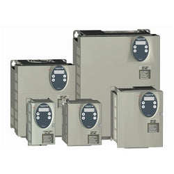
Main
| Characteristic | Value(s) |
|---|---|
| Range of Product | Altivar |
| Product or Component Type | Variable speed drive |
| Product Specific Application | Simple machine |
| Component name | ATV31 |
| Assembly style | With heat sink |
| EMC filter | Integrated |
| [Us] rated supply voltage | 200...240 V - 5...5 % |
| Supply frequency | 50...60 Hz - 5...5 % |
| Phase | Single phase |
| Motor power kW | 0.18 kW 4 kHz |
| Maximum Horse Power Rating | 0.25 hp 4 kHz |
| Line current | 3 A 200 V, Isc = 1 kA 2.5 A 240 V |
| Apparent power | 0.6 kVA |
| Prospective line Isc | 1 kA |
| Nominal output current | 1.5 A 4 kHz |
| Maximum transient current | 2.3 A 60 s |
| Power dissipation in W | 24 W at nominal load |
| Asynchronous motor control profile | Sensorless flux vector control with PWM type motor control signal Factory set : constant torque |
| Analogue input number | 3 |
Complementary
| Characteristic | Value(s) |
|---|---|
| Product destination | Asynchronous motors |
| Supply voltage limits | 170â¦264 V |
| Network Frequency | 47.5...63 Hz |
| Output frequency | 0.0005â¦0.5 kHz |
| Nominal switching frequency | 4 kHz |
| Switching frequency | 2...16 kHz adjustable |
| Speed range | 1â¦50 |
| Transient overtorque | 150â¦170 % of nominal motor torque |
| Braking torque | <= 150 % 60 s with braking resistor 100 % with braking resistor continuously 150 % without braking resistor |
| Regulation loop | Frequency PI regulator |
| Motor slip compensation | Suppressable Adjustable Automatic whatever the load |
| Output voltage | <= power supply voltage |
| Electrical connection | Al1, Al2, Al3, AOV, AOC, R1A, R1B, R1C, R2A, R2B, LI1...LI6 terminal 0.004 in² (2.5 mm²) AWG 14 L1, L2, L3, U, V, W, PA, PB, PA/+, PC/- terminal 0.004 in² (2.5 mm²) AWG 14 |
| Tightening torque | Al1, Al2, Al3, AOV, AOC, R1A, R1B, R1C, R2A, R2B, LI1...LI6 5.3 lbf.in (0.6 N.m) L1, L2, L3, U, V, W, PA, PB, PA/+, PC/- 7.08 lbf.in (0.8 N.m) |
| Insulation | Electrical between power and control |
| Supply | Internal supply for logic inputs 19...30 V 100 mA overload and short-circuit protection Internal supply for reference potentiometer (2.2 to 10 kOhm) 10...10.8 V 10 mA overload and short-circuit protection |
| Analogue input type | AI3 configurable current 0...20 mA 250 Ohm AI1 configurable voltage 0...10 V 30 V max 30000 Ohm AI2 configurable voltage +/- 10 V 30 V max 30000 Ohm |
| Sampling duration | LI1...LI6 4 ms discrete AI1, AI2, AI3 8 ms analog |
| Response time | AOV, AOC 8 ms analog R1A, R1B, R1C, R2A, R2B 8 ms discrete |
| Linearity error | +/- 0.2 % output |
| Analogue output number | 2 |
| Analogue output type | AOC configurable current 0...20 mA 800 Ohm 8 bits AOV configurable voltage 0...10 V 470 Ohm 8 bits |
| Discrete input logic | Positive logic (source) LI1...LI6), < 5 V, > 11 V Logic input not wired LI1...LI4), < 13 V Negative logic (source) LI1...LI6), > 19 V |
| Discrete output number | 2 |
| Discrete output type | Configurable relay logic R1A, R1B, R1C) 1 NO + 1 NC - 100000 cycles Configurable relay logic R2A, R2B) NC - 100000 cycles |
| Minimum switching current | R1-R2 10 mA 5 V DC |
| Maximum switching current | R1-R2 2 A 250 V AC inductive, cos phi = 0.4 7 ms R1-R2 2 A 30 V DC inductive, cos phi = 0.4 7 ms R1-R2 5 A 250 V AC resistive, cos phi = 1 0 ms R1-R2 5 A 30 V DC resistive, cos phi = 1 0 ms |
| Discrete input number | 6 |
| Discrete input type | LI1...LI6) programmable 24 V, 0â¦100 mA PLC 3500 Ohm |
| Acceleration and deceleration ramps | S, U or customized Linear adjustable separately from 0.1 to 999.9 s |
| Braking to standstill | By DC injection |
| Protection type | Input phase breaks drive Line supply overvoltage and undervoltage safety circuits drive Line supply phase loss safety function, for three phases supply drive Motor phase breaks drive Overcurrent between output phases and earth (on power up only) drive Overheating protection drive Short-circuit between motor phases drive Thermal protection motor |
| Insulation resistance | >= 500 mOhm 500 V DC for 1 minute |
| Display type | 1 LED Red)drive voltage Four 7-segment display unitsCANopen bus status |
| Time constant | 5 ms for reference change |
| Frequency resolution | Display unit 0.1 Hz Analog input 0.1...100 Hz |
| Connector type | 1 RJ45 CANopen via VW3 CANTAP2 adaptor 1 RJ45 Modbus |
| Physical interface | RS485 multidrop serial link CANopen via VW3 CANTAP2 adaptor RS485 multidrop serial link Modbus |
| Transmission frame | RTU CANopen via VW3 CANTAP2 adaptor RTU Modbus |
| Transmission Rate | 10, 20, 50, 125, 250, 500 kbps or 1 Mbps CANopen via VW3 CANTAP2 adaptor 4800, 9600 or 19200 bps Modbus |
| Number of addresses | 1â¦127 CANopen via VW3 CANTAP2 adaptor 1â¦247 Modbus |
| Number of drive | 127 CANopen via VW3 CANTAP2 adaptor 31 Modbus |
| Marking | CE |
| Operating position | Vertical +/- 10 degree |
| Product Weight | 3.3 lb(US) (1.5 kg) |